Batch reaction system

Inactive Publication Date: 2007-12-25
AVANTIUM INT
View PDF8 Cites 1 Cited by
  • Summary
  • Abstract
  • Description
  • Claims
  • Application Information

AI Technical Summary

Benefits of technology

[0005]It is an object of the invention to avoid the above and other problems and to provide a batch reaction system wherein all reactors may easily be isolated from one another during reaction or treatment.

Problems solved by technology

A problem that often occurs when using the known batch reaction system is that material from one reactor enters another reactor resulting in contamination.

Method used


Image

  • Batch reaction system
  • Batch reaction system

Examples


Embodiment Construction

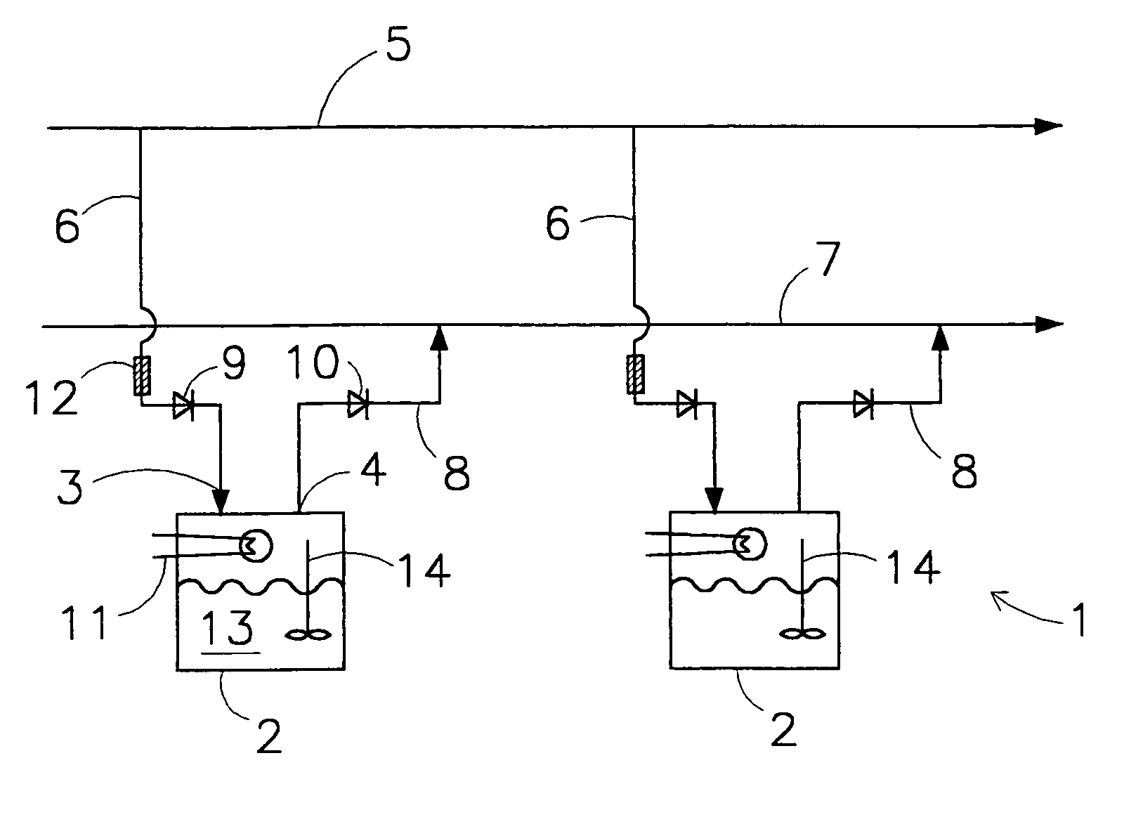
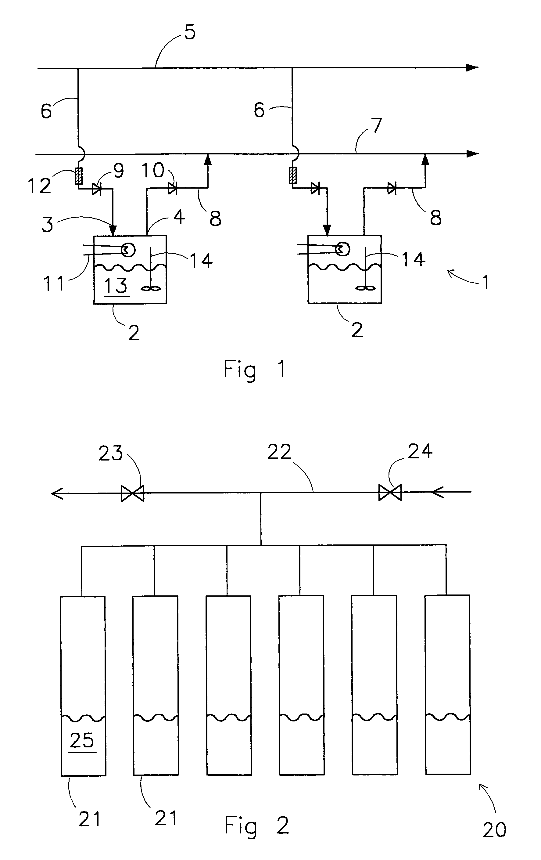
[0037]FIG. 1 shows a schematic cross-sectional view of the batch reaction system 1 according to the invention for simultaneously conducting reactions in at least two separate, parallel batch reactors 2, in the shown embodiment in a closed system. In FIG. 1 only two batch reactors 2 are shown. The person skilled in the art will however readily understand that more than two, usually at least ten, batch reactors 2 may be used. Important according to the invention is that the reactors 2 can be isolated from the atmosphere.

[0038]Each batch reactor 2 contains mixing means 14, a fluid inlet 3 and a gas outlet 4. In this respect it is noted that the outlet 4, which may also be a fluid outlet, is, although preferred, not essential; i.e. the outlet 4 may, according to the invention, also be omitted. As mixing means 14, any suitable means may be used, in particular mechanical mixing means, such as a magnetic stirrer, overhead stirrer, orbital shaker or ultrasound. The system 1 further comprise...


PUM

PropertyMeasurementUnit
temperatureaaaaaaaaaa
pressureaaaaaaaaaa
volatileaaaaaaaaaa

Abstract

A batch reaction system for simultaneously conducting reactions in at least two separate reactors (CSTR reactors), is provided wherein the at least two batch reactors, containing mixing means and a fluid inlet, a fluid feed common conduit is present for feed fluid to the reactors, which is connected to the inlet of each reactor of a fluid inlet conduits, and further includes a fluid discharge common conduit which is connected to the outlet of each reactor wherein in each fluid inlet conduit and/or in each fluid outlet conduit a non-return valve is arranged to prevent contamination but can provide simultaneous reactions wherein the reactors can be easily isolated from one another during reaction.

Description

RELATED APPLICATIONS[0001]This application in a continuation-in-part of prior application No. PCT / EP02 / 13896 filed Dec. 6, 2002, which application claims priority to and the benefit of EP01204736.1 filed Dec. 7, 2001.FIELD OF THE INVENTION[0002]The invention relates to a batch reaction system for simultaneously conducting reactions in at least two separate reactors. The invention also relates to a process wherein use is made of such a batch reaction system.BACKGROUND OF THE INVENTION[0003]In practice many different batch reaction systems are known. In known batch reaction systems a gas feeding common conduit is used to feed gas to several parallel reactors and a gas discharge common conduit is used to discharge gas from these parallel reactors.[0004]A problem that often occurs when using the known batch reaction system is that material from one reactor enters another reactor resulting in contamination. This for instance occurs when a volatile liquid is treated or reacted in a reacto...

Claims


Application Information

Patent Timeline
Patent Type & Authority Patents(United States)
IPC IPC(8): B01J8/04B01J19/00C40B60/14
CPCB01J19/0046C40B60/14B01J2219/00283B01J2219/00337B01J2219/00389B01J2219/00477B01J2219/00479B01J2219/00481B01J2219/00484B01J2219/00486B01J2219/00495B01J2219/00585B01J2219/00596B01J2219/00601B01J2219/00698B01J2219/0072B01J2219/00038
Inventor NAGY, ANTON JOHNVAN DEN BRINK, PETER JOHNHARJI, BASHIR HUSEIN
Owner AVANTIUM INT
Why Eureka
Try Eureka