Network System, Cable Set, and Method and Program for Controlling Network System

a network system and cable technology, applied in the direction of digital output to print units, instruments, data switching details, etc., can solve the problems of power supply circuit breakdown, no means to determine, and cannot be expected to overload in advance, so as to facilitate the replacement of printers

Inactive Publication Date: 2009-10-22
SEIKO EPSON CORP
View PDF9 Cites 50 Cited by
  • Summary
  • Abstract
  • Description
  • Claims
  • Application Information

AI Technical Summary

Benefits of technology

[0193]According to this configuration, location information for identifying the location is determined for a location where the printer is arranged, and the location information is assigned to the corresponding location. Then, the printer arranged at the location reads the location information to obtain the location information, and it is possible to obtain the network address on the basis of the location information. If this network address is associated with the corresponding POS register, the printer which has obtained this network address can be operated in cooperation with the POS register. In this manner, by simply associating the printer with the recording means of the location information for the arrangement, the printer obtains the network address, and a state in which a communication can be established is attained. Therefore, even those having no knowledge of the setting for the network address can easily replace the printers.

Problems solved by technology

On the other hand, the overload protection apparatus disclosed in the second background art is adapted to prevent the overload during the power supply, but the overload cannot be expected in advance.
That is, with respect to a power supply request from a side receiving a power supply feed, in a case where a power supply output capacity on a side performing the power supply feed is too large, there is a fear that a breakdown of a power supply circuit due to the overload, but there is no means to determine this situation.

Method used


Image

  • Network System, Cable Set, and Method and Program for Controlling Network System
  • Network System, Cable Set, and Method and Program for Controlling Network System
  • Network System, Cable Set, and Method and Program for Controlling Network System

Examples


first embodiment

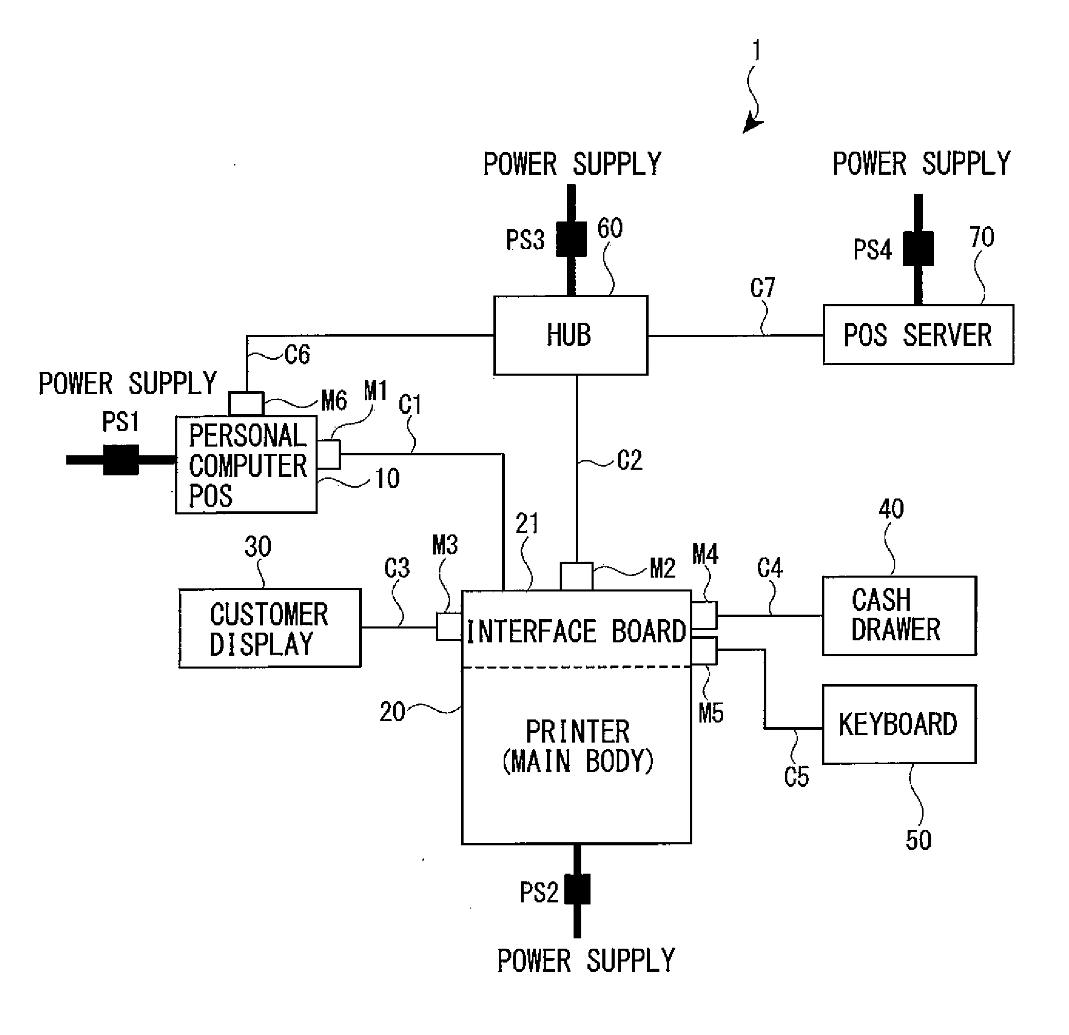
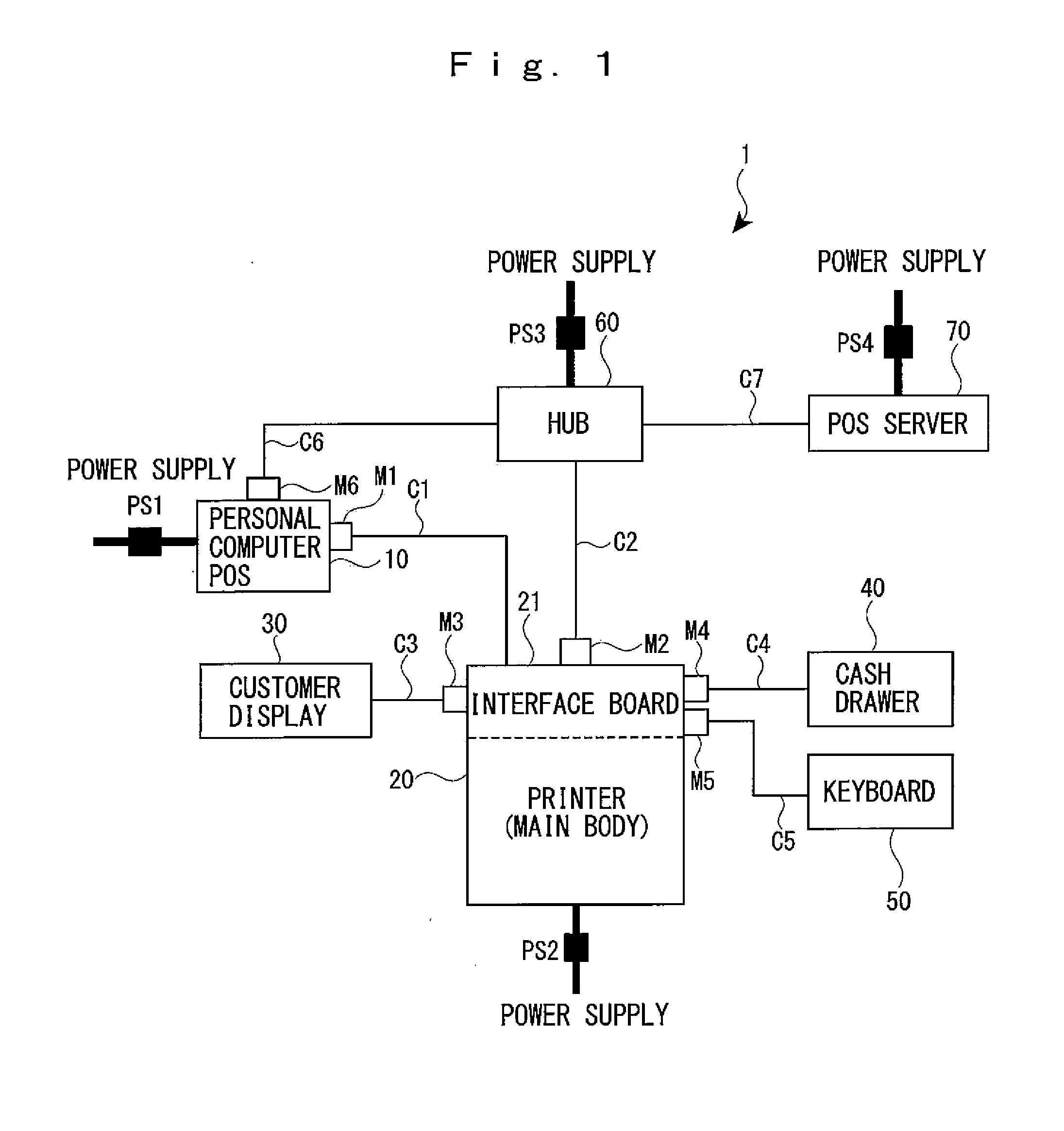
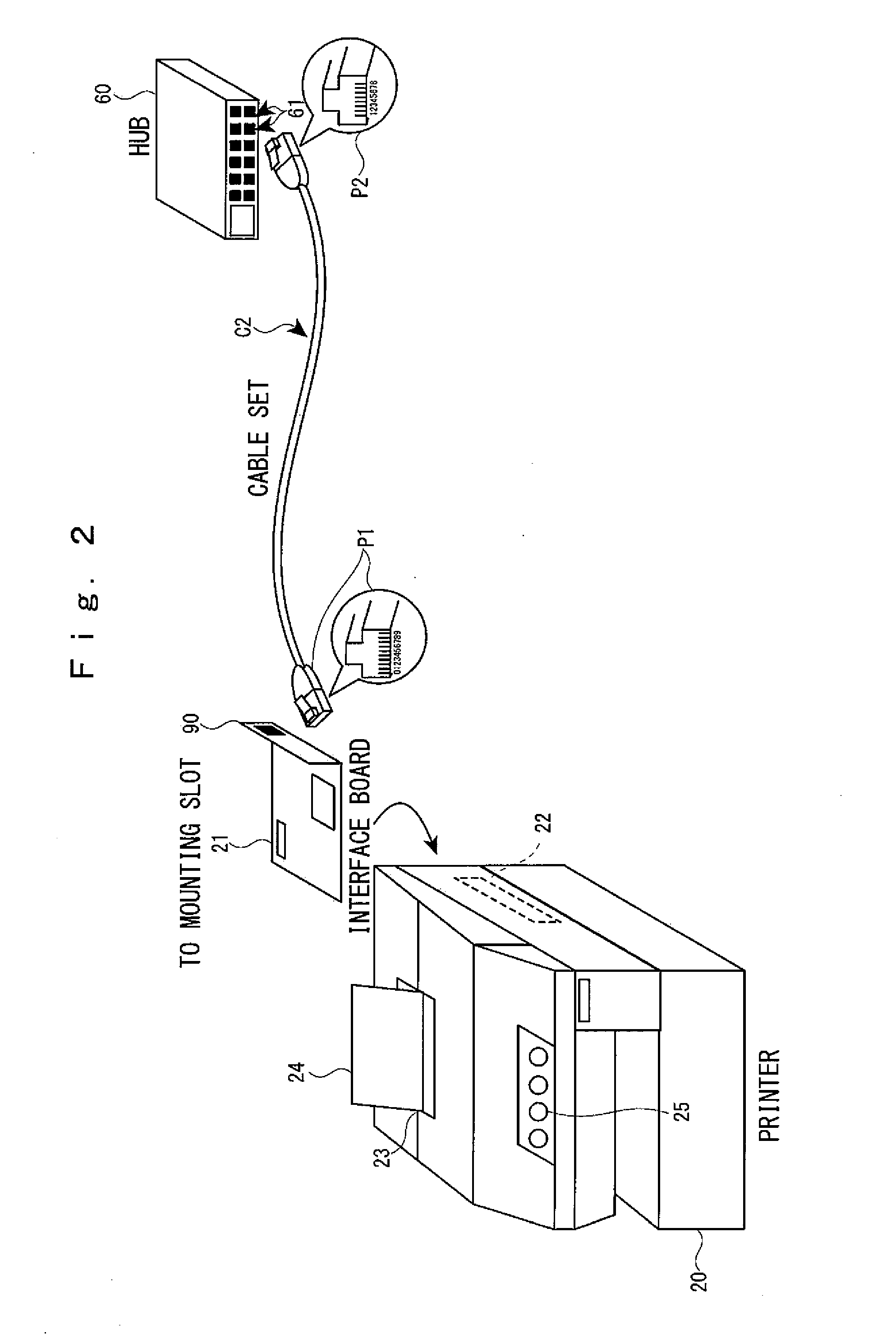
[0216]Non-volatile memory modules M1 to M6 storing various pieces of information are mounted to plugs P of cable sets C1 to C6 for connecting the respective devices (refer to FIG. 2). The information stored in the non-volatile memory module M and a use method therefor will be described in detail in each embodiment. First, an initial setting method for a device using the non-volatile memory module M will be described. Any type of the device which perform the initial setting may be employed, but a description will be given by way of an example of an initial setting method for the printer 20 using the cable set C2 (a network system 101, refer to FIG. 5).

[0217]FIG. 2 is a perspective external view of the printer 20 (main body), the interface board 21, and the cable set C2. As shown in FIG. 2, the printer 20 is provided with a mounting slot 22 for mounting the interface board 21 at its back face part and also a discharge port 23 for discharging the receipt or the voucher at its upper su...

second embodiment

[0275]FIG. 14 is a block diagram showing a control configuration for the power supply feed system 201 according to a As described above, the power supply feed system 201 is composed of the keyboard 50, the printer 20, and the cable set C5. Among them, the keyboard 50 is equivalent to a device which needs the power supply feed (the first device), and the printer 20 is equivalent to a device which performs the power supply feed (the second device).

[0276]The keyboard 50 is provided with a connecting port 59. The connecting port 59 is provided with a normal use communication line 53. Also, the normal use communication line 53 includes a power supply line for receiving the power supply feed and a signal line for performing a communication with the printer 20.

[0277]The cable set C5 is provided with a plug P201 on the printer side. It should be noted that the cable set C5 of course has a plug on the keyboard side as well, but this is not particularly related to the gist of the invention. ...

third embodiment

[0302]FIG. 16 is a block diagram for showing a control configuration for the network system 301 according to a As described above, the network system 301 is constructed by the hub 60, the printer 20, and the cable set C2.

[0303]The hub 60 is provided with address filter setting means 64 and a connecting port 69. The connecting port 69 includes a normal use communication line 63. That is, in a case of using the 100BASE-T4 standard cable shown in FIG. 6, an eight pin connector is provided.

[0304]The address filter setting means 64 secures the security of the network system 301 by restricting communications other than a communication by a device having the registered MAC address to set a so-called “MAC address filtering”. At this time, as shown in FIG. 17, instead of the MAC address of the device connected to the hub 60 (the personal computer POS 10 and the printer 20), the MAC address of the cable set C2 (hereinafter referred to as “cable address”) is registered. Therefore, two address...


PUM


Abstract

A network system is provided with a cable set having a nonvolatile memory module mounted thereon, and a printer connected by the cable set. The printer is provided with a set information read means for reading set information for performing initial setting of itself from a nonvolatile memory module of the connected cable set, and an initial setting means for performing initial setting based on the read set information.

Description

TECHNICAL FIELD[0001]The present invention relates to a network system including devices and a cable set for connecting the devices or an RFID enabling a wireless communication, a cable set, and a method and a program for controlling network system.BACKGROUND ARTFirst Background Art[0002]In a network system in which a plurality of devices are connected, in order to identify devices which become communication targets, a control address such as an IP address is written or a hardware address uniquely allocated to an apparatus such as a MAC address is used. For this reason, in a case where a device is replaced or an arrangement change of the device is performed, each time, it is necessary to conduct an initial setting by assigning an IP address to a new device or registering an MAC address allocated to a new device.[0003]However, the initial setting of this type is difficult for an ordinary user to conduct and it is necessary to ask a service company, which leads to a high maintenance c...

Claims


Application Information

Patent Timeline
Patent Type & Authority Applications(United States)
IPC IPC(8): G06F15/00H04Q5/22
CPCH04L12/10H04L29/12207H04L29/12301H04L29/12839G06F3/1224H04L61/2076H04L61/6022H04L67/125H04L41/0806H04L61/50H04L61/5076H04L2101/622
Inventor NOBUTANI, TSUTOMU
Owner SEIKO EPSON CORP
Why Eureka
Try Eureka