
Noise removal device and noise removal method

a noise removal device and noise removal technology, applied in pulse technique, phase-modulated carrier system, baseband system details, etc., can solve the problems of inability to achieve satisfactory correction, inability to reduce noise satisfactorily with linear interpolation scheme, and deterioration of audio quality of radio signal received by the radio receiver

Inactive Publication Date: 2009-10-22
RENESAS ELECTRONICS CORP
View PDF19 Cites 2 Cited by
  • Summary
  • Abstract
  • Description
  • Claims
  • Application Information

AI Technical Summary

Benefits of technology

The present invention is about a device and method for removing noise from an input signal. The device includes a noise detector, an interpolation controller, and a noise gate processor. The interpolation controller determines the period and amount of interpolation needed for noise correction based on the input signal and the noise detection signal. The noise gate processor performs the noise correction processing based on the interpolation period and the interpolation amount. The invention allows for revision of the noise interpolation period when a new noise event is detected within the interpolation period, resulting in more proper interpolation and improved noise removal.

Problems solved by technology

In an in-vehicle radio receiver, when pulse noise such as ignition noise generated by the engine of a vehicle gets into an in-vehicle radio receiver, the audio quality of a radio signal received by the radio receiver is deteriorated.
However, when the period in which noise is generated is long, the noise cannot be reduced satisfactorily with the linear interpolation scheme.
As a result, not only satisfactory correction fails to be performed, but a large correction error might even result.
For this reason, it is sometimes difficult for the noise removal device of Patent Document 1 to handle high frequency pulse noise having short cycles, such as noise generated from a door mirror drive motor or a hazard flasher.
Accordingly, a large correction error is caused.
Consequently, a large correction error is caused.
When the interpolation scheme is selected based on the state of the end point of the correction period, proper correction cannot be performed for noise events included successively at a short interval.
However, a proper correction period cannot be obtained with this revision method when the above-described correction period signal is shorter than the pulse-noise generation period, or when the signal includes pulse noise events successively at a short interval.
As described, in some cases, correction cannot be performed on a noise event that occurs after the correction period.

Method used


Image

  • Noise removal device and noise removal method
  • Noise removal device and noise removal method
  • Noise removal device and noise removal method

Examples


embodiment 1

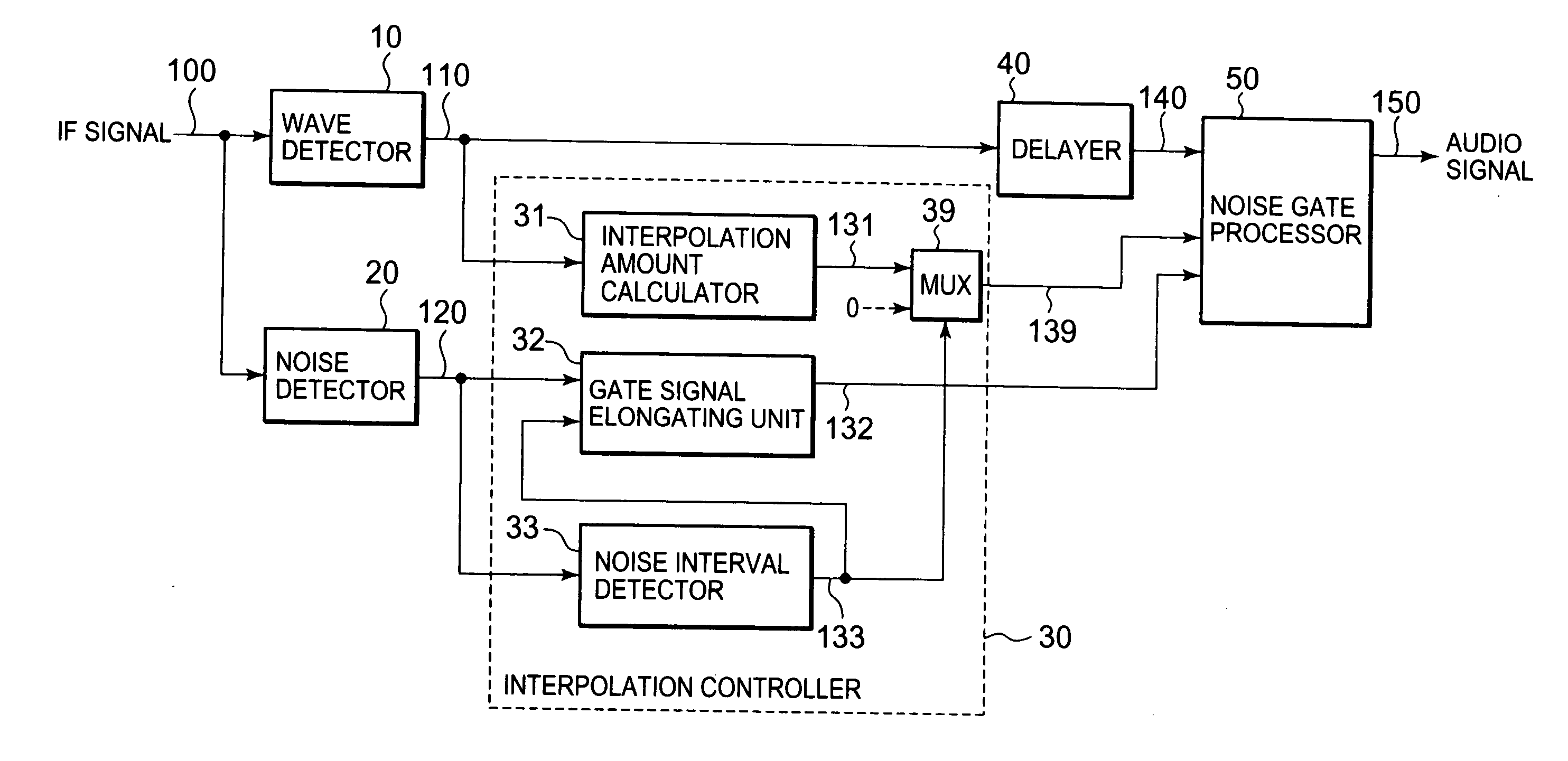
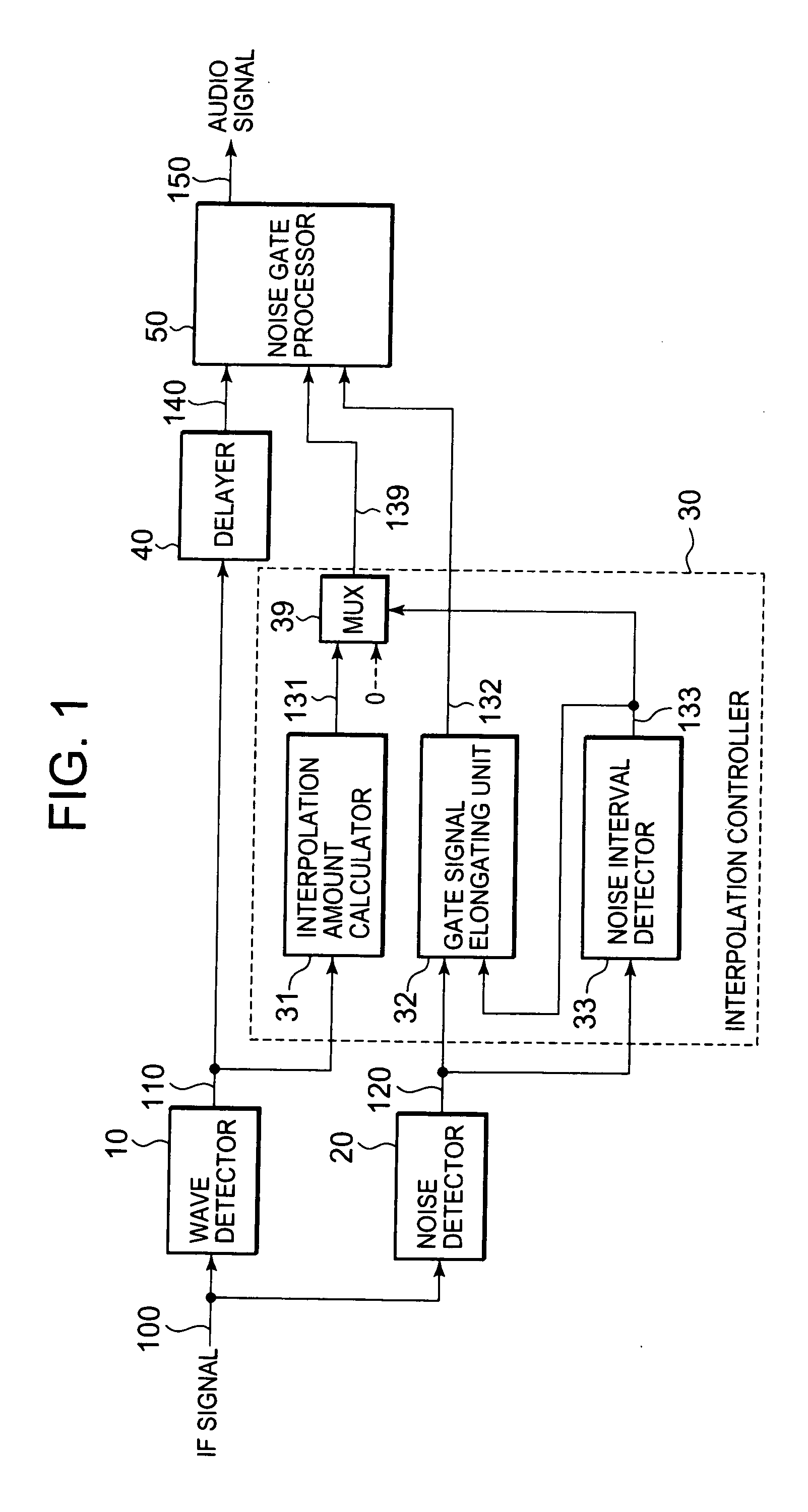
[0032]Using FIG. 1, a description will be given first of the configuration of a noise removal device according to Embodiment 1. FIG. 1 is a block diagram showing the configuration of the noise removal device according to Embodiment 1. In FIG. 1, the noise removal device according to Embodiment 1 includes a wave detector 10, a noise detector 20, an interpolation controller 30, a delayer 40, and a noise gate processor 50.

[0033]An intermediate frequency (IF) signal 100 for a radio receiver is supplied to the wave detector 10 and to the noise detector 20. The wave detector 10 detects (demodulates) the IF signal 100, and extracts a wave detection signal 110 therefrom. At this time, the wave detector 10 also enhances noise components included in the IF signal 100.

[0034]The delayer 40 receives the wave detection signal 110 and delays it for a given length of time, and outputs a delay signal 140. The delayer 40 is provided to compensate for time necessary for preparation for noise correctio...

embodiment 2

[0058]Using FIG. 4, a description will be given of a noise removal device according to Embodiment 2. FIG. 4 is a block diagram showing the configuration of the noise removal device according to Embodiment 2. The configuration of the interpolation controller 30 of Embodiment 2 is different from that of Embodiment 1. As other configurations are the same as Embodiment 1, their descriptions will be omitted.

[0059]In FIG. 4, the interpolation controller 30 of the noise removal device according to Embodiment 2 further includes a counter 34. The counter 34 disables the operation of redefining the interpolation period when a count value of noise detection within the interpolation period reaches a certain value. In other words, when the number of the noise interval detection signals 133 inputted into and counted by the counter 34 reaches a predetermined count value, the counter 34 outputs a disabling signal 134 for causing the gate signal elongating unit 32 not to perform the interpolation pe...

embodiment 3

[0062]Using FIG. 5, a description will be given of a noise removal device according to Embodiment 3. When interpolation is performed on the IF signal 100 having rather high amplitude, the use of the previous-value hold scheme may cause a large step of difference in noise level at the endpoint of the interpolation period. This rather deteriorates the audio quality. In this respect, the noise removal device of Embodiment 3 is configured so that the linear interpolation scheme can be selected depending on the level of the input signal. FIG. 5 is a block diagram showing the configuration of the noise removal device according to Embodiment 3. The noise removal device of Embodiment 3 has a configuration in which a level detector 60 is further included in the configuration of Embodiment 1. As other configurations are the same as Embodiment 1, their descriptions will be omitted.

[0063]In FIG. 5, the IF signal 100 is supplied to the wave detector 10, to the noise detector 20, and to the level...


PUM


Abstract

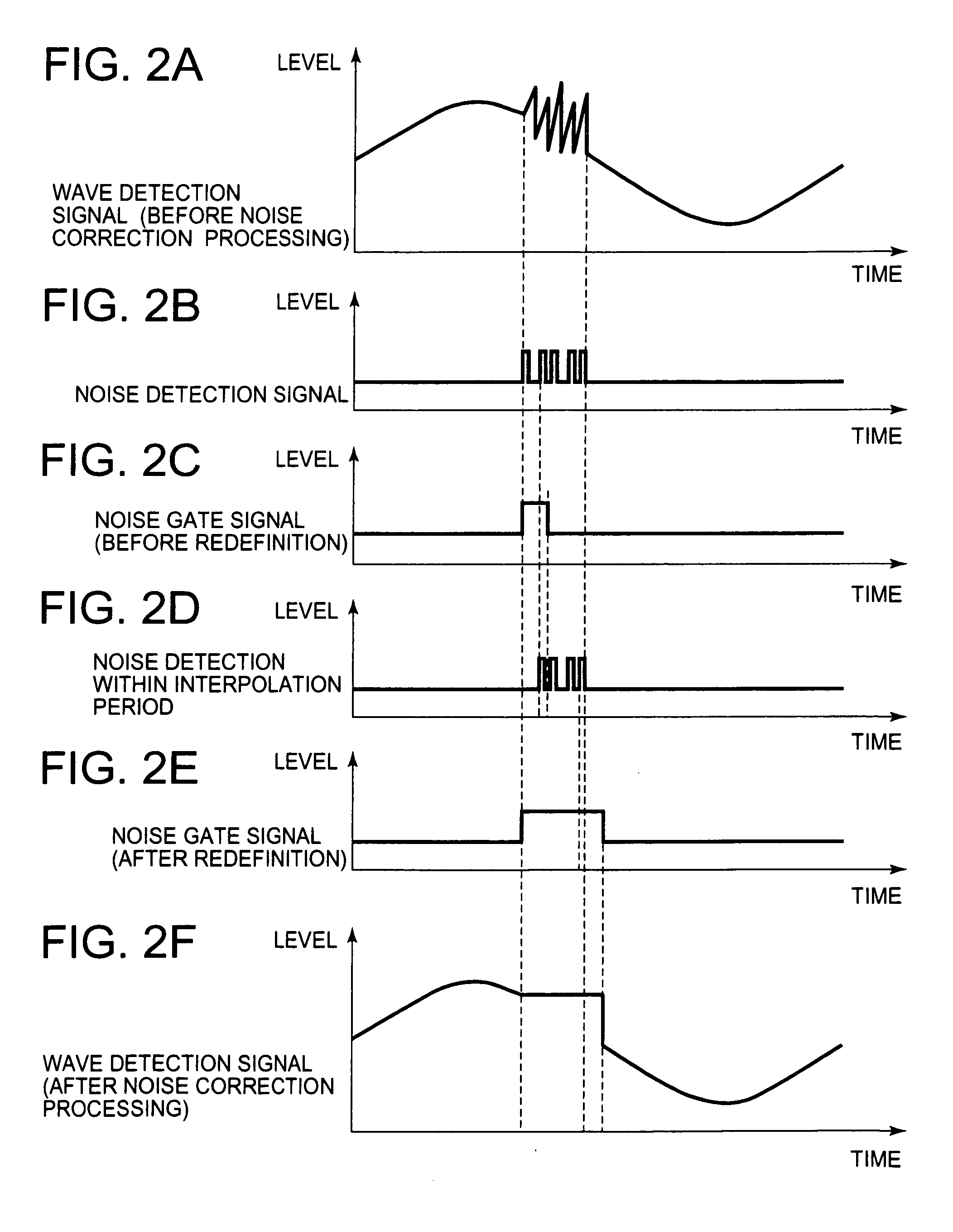
The invention provides a noise removal device and method capable of more proper interpolation on an input signal. The noise removal device is for removing noise in an input signal and includes: a noise detector detecting noise in an IF signal and outputting a noise detection signal; an interpolation controller determining a period and amount of interpolation for noise correction processing, based on the IF signal and the noise detection signal; and a noise gate processor performing the noise correction processing on the IF signal, based on the interpolation period and amount supplied from the interpolation controller. The interpolation controller sets a predetermined first interpolation period, based on a first noise detection signal inputted from the noise detector, and redefines a second interpolation period longer than the first interpolation period when a second noise detection signal is detected within the first interpolation period.

Description

BACKGROUND OF THE INVENTION[0001]1. Field of the Invention[0002]The present invention relates to a noise removal device and a noise removal method, and more specifically, to a noise removal device and a noise removal method for removing noise generated in a radio receiver.[0003]2. Description of the Related Art[0004]In an in-vehicle radio receiver, when pulse noise such as ignition noise generated by the engine of a vehicle gets into an in-vehicle radio receiver, the audio quality of a radio signal received by the radio receiver is deteriorated. For this reason, the radio receiver is provided with a noise removal device for removing such pulse noise from a reception signal.[0005]In the noise removal device, correction is performed on an audio signal in which noise is generated, by using a scheme such as a previous-value hold scheme or an interpolation scheme between two known points (linear interpolation scheme). In the linear interpolation scheme, the point at which noise is detect...

Claims


Application Information

Patent Timeline
Patent Type & Authority Applications(United States)
IPC IPC(8): H04B1/10
CPCH03G3/345
Inventor SUEZAWA, TAKAAKI
Owner RENESAS ELECTRONICS CORP
Learn More