Microwave combustion system for internal combustion engines

a combustion system and internal combustion engine technology, applied in the direction of electric/magnetic/electromagnetic heating, sparking plugs, lighting and heating apparatus, etc., can solve the problems of loss of power (i.e., efficiency), increased pollution, and complex system

Inactive Publication Date: 2009-10-29
BTU INTERNATIONAL
View PDF8 Cites 35 Cited by
  • Summary
  • Abstract
  • Description
  • Claims
  • Application Information

AI Technical Summary

Benefits of technology

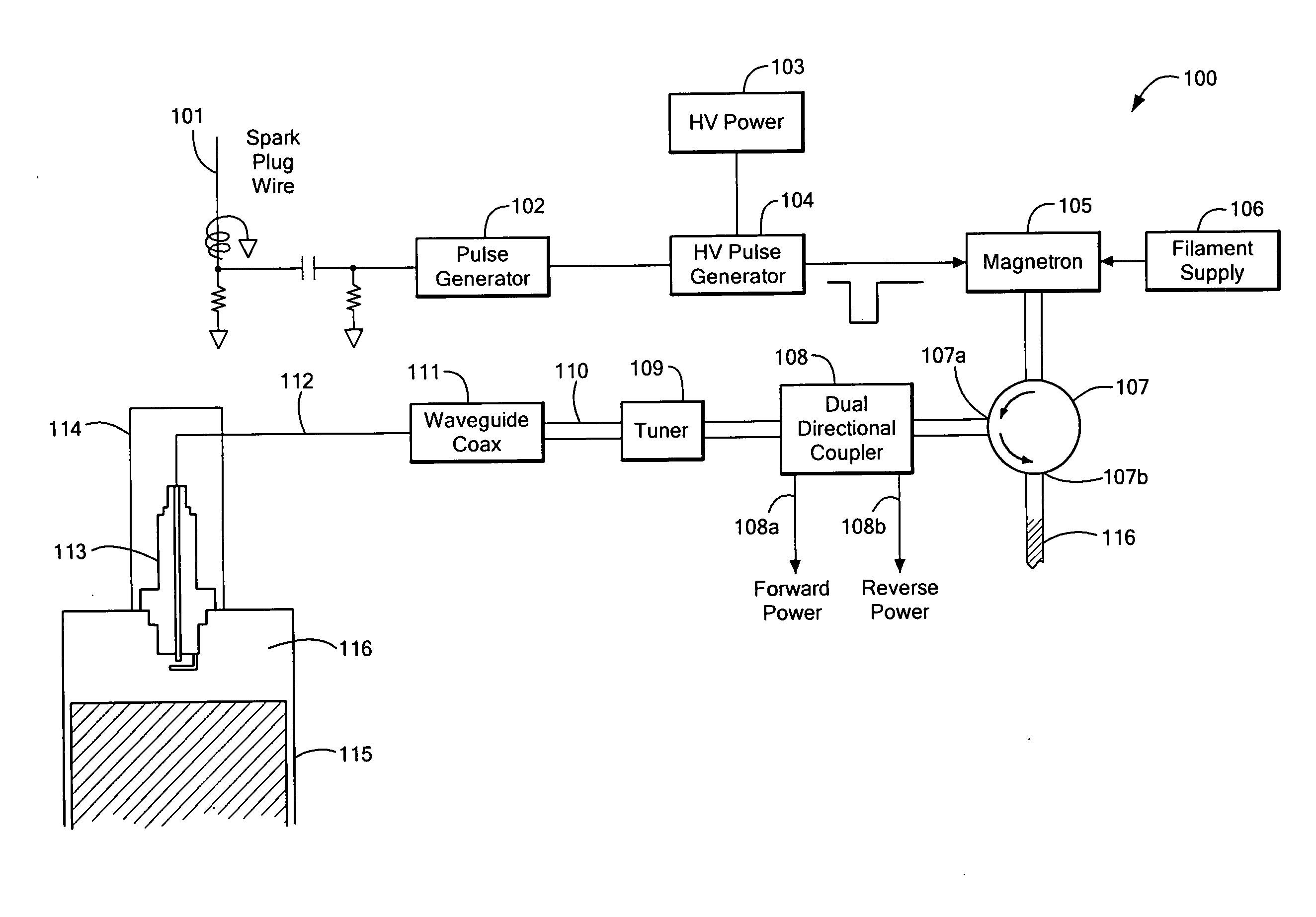
[0010]The microwave combustion system may include a circulator coupled between the microwave source and the plug. The microwave combustion system may further include a dual directional coupler to help monitor forward and reverse propagating microwave energy coupled between the microwave source and the plug. The microwave combustion system may further include a tuner coupled between the microwave source and the plug.

Problems solved by technology

Inefficient combustion results in loss of power (i.e., efficiency) and greater pollution due to incomplete fuel usage.
Such a system is highly complicated as it requires both a microwave system and a conventional high-voltage delivery system to the spark plug.

Method used


Image

  • Microwave combustion system for internal combustion engines
  • Microwave combustion system for internal combustion engines
  • Microwave combustion system for internal combustion engines

Examples


Embodiment Construction

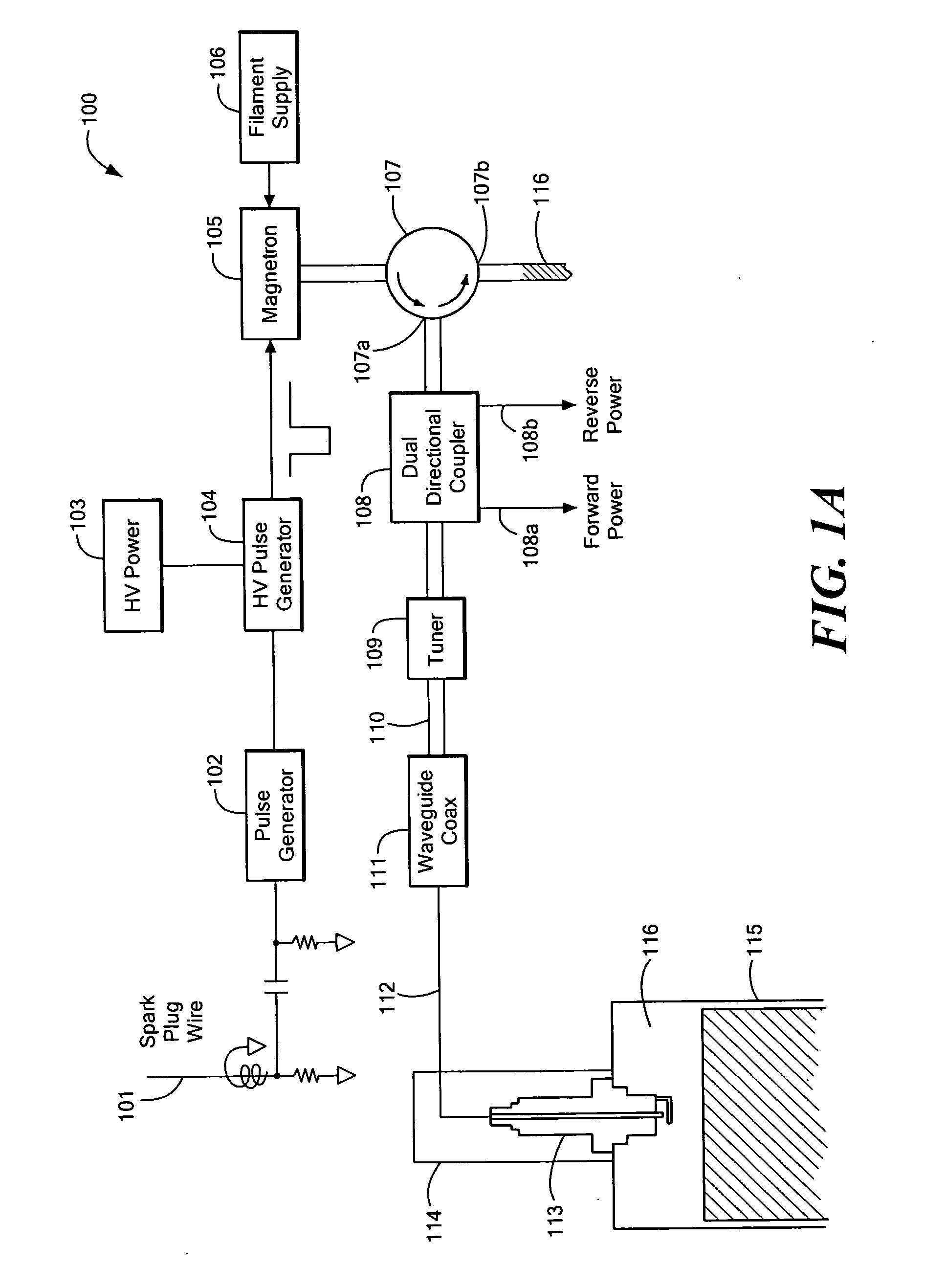
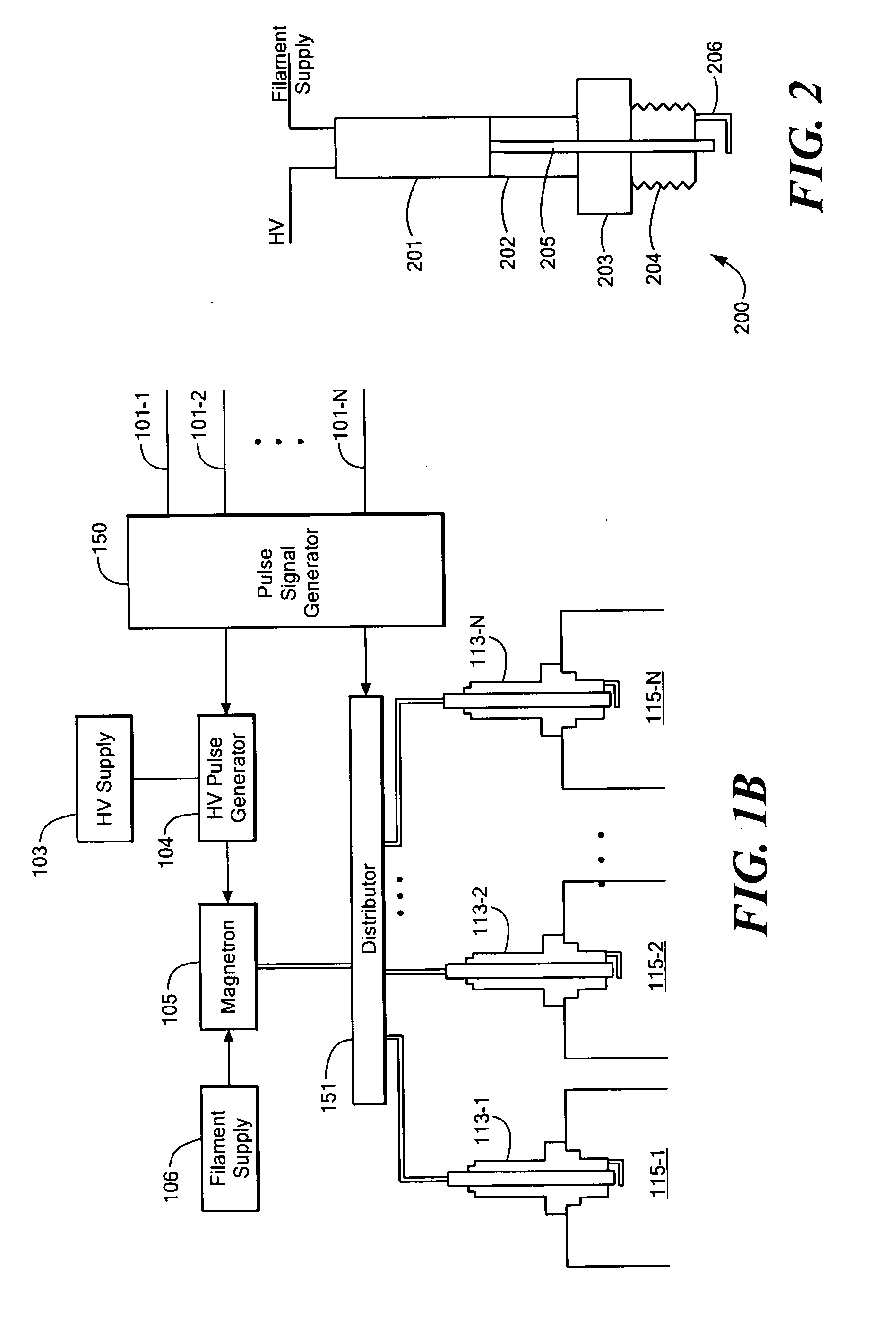
[0025]FIG. 1A illustrates a microwave combustion system according to some embodiments of the present invention. An embodiment of the system illustrated in FIG. 1A, for example, has been utilized successfully to operate a single-cylinder lawnmower engine.

[0026]As shown in FIG. 1A, a spark plug wire 101 that would normally connect directly to a spark plug 113 and provide the necessary 10-30 kV high voltage pulse to generate a spark in volume 116 of a cylinder 115 is instead coupled to a pulse generator 102. In some embodiments, the pulse generator 102 may be coupled to an engine control unit or other pick-up synchronized with the rotation of the engine rather than to the spark plug wire 101. The pulse generator 102, in response to the downward edge of the pulse on spark plug wire 101, generates a control pulse to a high-voltage pulse generator 104. The pulse generator 104 can be a high voltage switching device that can couple a high voltage power supply 103 to a microwave source 105. ...


PUM


Abstract

A microwave combustion system is presented that can replace the conventional spark plug in an internal combustion engine. One or more microwave pulses are provided to a microwave feed in a plug that sits in the cylinder. A microwave generated plasma generated by the plug in the vicinity of a fuel mixture can provide for highly efficient combustion of the fuel-air mixture.

Description

CROSS REFERENCE TO RELATED APPLICATIONS[0001]This application claims the benefit under 35 U.S.C. § 119(e) of U.S. Provisional Application No. 60 / 715,747, filed Sep. 9, 2005, the disclosure of which is incorporated by reference herein.STATEMENT REGARDING FEDERALLY SPONSORED RESEARCH OR DEVELOPMENT[0002]N / ABACKGROUND OF THE INVENTION[0003]In internal combustion engines, both the efficiency and pollution characteristics of the engine are highly dependent on the efficient combustion of the fuel-air mixture in the cylinders. Inefficient combustion results in loss of power (i.e., efficiency) and greater pollution due to incomplete fuel usage.[0004]In conventional gas engines, the fuel-air mixture is ignited by a spark plug that provides a spark to the mixture when a high voltage (i.e. 10-30 kV) is applied across a spark gap of a spark plug. The application of the high voltage is timed for when the cylinder volume (and therefore the fuel-air mixture) is close to as low a volume as possible...

Claims


Application Information

Patent Timeline
Patent Type & Authority Applications(United States)
IPC IPC(8): F02B19/00
CPCH01T13/50F02P23/045F02B7/00F02P3/01
Inventor KUMAR, DEVENDRATASCH, DOMINIQUEPEELAMEDU, RAMESHKUMAR, SATYENDRABROSKY, DAVIDGREGERSEN, MICHAEL
Owner BTU INTERNATIONAL
Why Eureka
Try Eureka