Apparatus and Method For Using Spacer Paste to Package an Image Sensor

a technology of image sensor and spacer, which is applied in the direction of electrical apparatus, semiconductor/solid-state device manufacturing, semiconductor devices, etc., can solve the problems of increasing manufacturing costs, wasting space on the die, and difficult control of conventional liquid adhesive thickness and width

Active Publication Date: 2009-10-29
OMNIVISION TECH INC
View PDF15 Cites 56 Cited by
  • Summary
  • Abstract
  • Description
  • Claims
  • Application Information

AI Technical Summary

Benefits of technology

[0006]A packaged image sensor assembly utilizes a spacer paste to control the height of a transparent window above an image sensor die to provide safe wire bond clearance. An image sensor die is mounted to an interposer and wire bonds are formed between the image sensor die and the interposer. A transparent cover is attached to the image sensor die using a dam formed from a spacer paste. The dam may be formed either entirely from spacer paste or from spacer paste dispensed on top of an underlying patterned mesa region. The spacer paste provides a uniform, low-tilt bonding surface having a controlled height above the surface of the image sensor to provide wire bond clearance. An additional encapsulant may be formed in a region outside of the dam in a region between the transparent cover and the interposer.

Problems solved by technology

Conventional liquid adhesives are difficult to control in regards to thickness and width.
Thus, the width of the liquid adhesive is greater than desired, wasting space on the die and thereby increasing manufacturing costs.
However, it is difficult to accurately control the spreading of a large area liquid resin film due to resin bleed.
That is, in addition to other drawbacks a film made of a liquid resin will tend to flow laterally across the edge of the die after an initial film deposition.
As a result, this means that it is difficult to achieve a narrow gap between the pixel array edge and the die edge.
This wastes die area which, in turn, results in greater manufacturing costs than desired.
Additionally, moisture permeation of a liquid adhesive resin film is a reliability concern.
In particular, there is a risk that moisture can permeate laterally through the resin film during the lifetime of the packaged image sensor.

Method used


Image

  • Apparatus and Method For Using Spacer Paste to Package an Image Sensor
  • Apparatus and Method For Using Spacer Paste to Package an Image Sensor
  • Apparatus and Method For Using Spacer Paste to Package an Image Sensor

Examples


Embodiment Construction

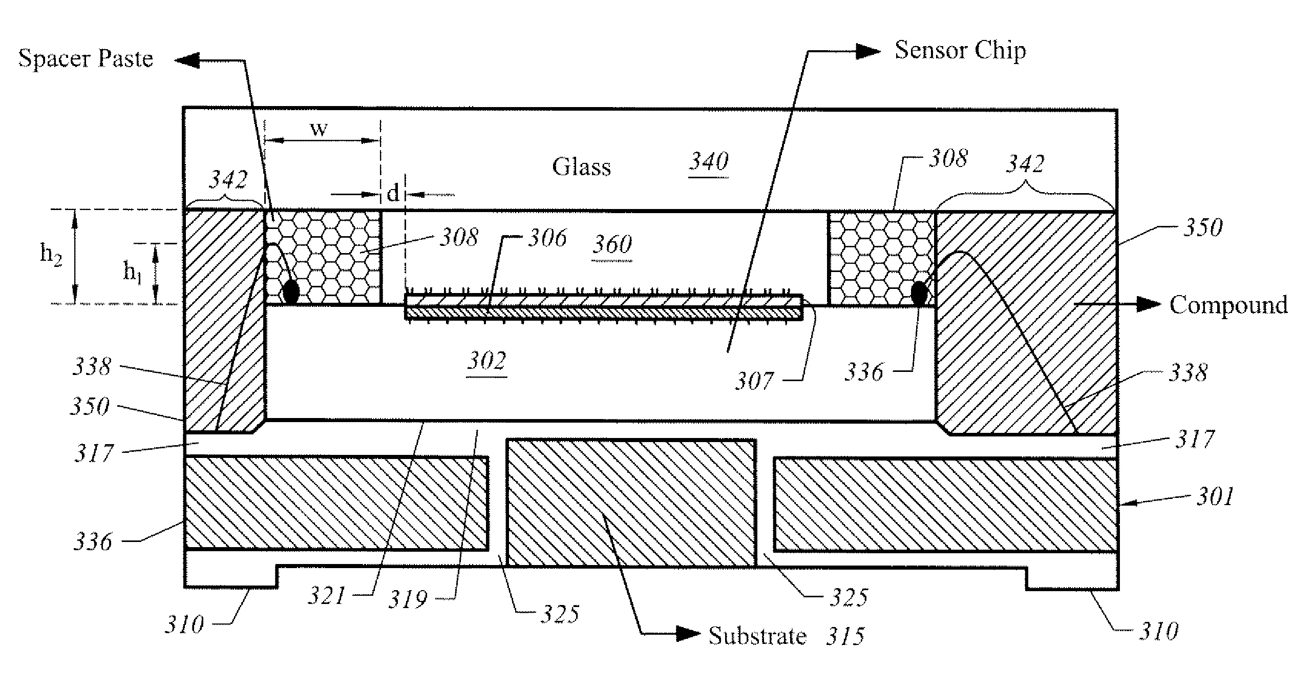
[0013]FIG. 3A is a top view of a packaged image sensor 300 through a top transparent cover 340. The top transparent cover 340 permits light to reach an array of photo-sensitive pixels 306 located in a central portion 304 of an image sensor die 302, where the image sensor die 302 is an integrated circuit chip. An encapsulant 350 is formed under a peripheral portion of the transparent cover 340. A spacer paste dam 308 is formed by a spacer paste epoxy located on a peripheral edge portion of image sensor die 302 that does not obstruct the central portion 304 that contains the array of pixels 302. Dam 308 has a width, w. The array of pixels 306 may continue up to the boundary of dam 308 but more generally a slight offset, d, may be provided to account for manufacturing tolerances. Thus, the edge of the array of pixels 306 is inset from the edge of the image sensor die 302 by a total distance of: w+d. For the purposes of illustrating some aspects of the invention dashed lines (phantom li...


PUM


Abstract

A packaged image sensor assembly utilizes a spacer paste to control the height of a transparent window above an image sensor die to provide safe wire bond clearance. A dam structure is used to control the height of the transparent window. The dam may be formed either entirely from spacer paste or by depositing the spacer paste on an underlying patterned mesa. An additional encapsulant is provided outside of the dam to encapsulate wirebonds and provide additional protection from moisture permeation.

Description

FIELD OF THE INVENTION[0001]The present invention is generally related to the packaging of image sensors to encapsulate wire bonds and protect the image sensor from moisture. More particularly, the present invention is directed towards a packaged image sensor assembly that includes a dam structure and that provides wire bond encapsulation.BACKGROUND OF THE INVENTION[0002]Image sensors utilize an array of photo-sensitive pixels to capture an optical image. One common type of image sensor is a Complementary Metal Oxide Semiconductor (CMOS) image sensor. There are a variety of techniques to package CMOS image sensors. However, one technique that is used is to mount the image sensor on a substrate (interposer) and to provide wire bond connections between the substrate and the image sensor. An additional transparent cover is often provided to protect the image sensor.[0003]Reliability of the packaged image sensor is typically increased if the packaged assembly is encapsulated. One approa...

Claims


Application Information

Patent Timeline
Patent Type & Authority Applications(United States)
IPC IPC(8): H01L31/0203H01L31/18
CPCH01L27/14618H01L27/14683H01L2924/1815H01L2224/45144H01L2924/15311H01L2224/48465H01L2224/48227H01L2224/48091H01L31/0203H01L2924/00014H01L2924/00
Inventor CHIEN, YEH-ANLIN, WEI-FENG
Owner OMNIVISION TECH INC
Why Eureka
Try Eureka