
Composite Preform Having a Controlled Fraction of Porosity in at Least One Layer and Methods for Manufacture and Use

a technology of at least one layer and a controlled fraction, applied in the field of composite preforms, to achieve the effect of reducing the probability of failur

Inactive Publication Date: 2009-10-29
BODYCOTE IMT INC
View PDF35 Cites 18 Cited by
  • Summary
  • Abstract
  • Description
  • Claims
  • Application Information

AI Technical Summary

Benefits of technology

[0012]For example, carbon steel and Inconel 625, a highly corrosion resistant nickel-based superalloy, have flow stresses that normally are so different as to be incompatible for trouble free plastic deformation processing. By practice of the invention, the porosity of Inconel 625 in a billet with carbon steel can be adjusted to a predetermined level to decrease the flow stress of the Inconel 625 and provide a flow stress ratio of Inconel 625 to carbon steel of less than 2.3. Flow of Inconel 625 during processing should be concentric and the potential for failure during process diminished under these conditions.
[0014]HIPing, or other techniques of applying controlled pressure, temperature, and time, including cold isostatic pressing (“CIPing”) followed by application of heat by sintering, creates a metallurgical bond between the powder particles and controls the pore volume within the resulting PM component, thus also controlling the flow stress of that component. By controlling the pore fraction within specific layers or components that make up a billet, the flow stresses of the components can be controlled so that they are sufficiently close. Then the bicomponent billet can undergo plastic deformation and yield the desired product.

Problems solved by technology

For example, carbon steel and Inconel 625, a highly corrosion resistant nickel-based superalloy, have flow stresses that normally are so different as to be incompatible for trouble free plastic deformation processing.

Method used


Image

  • Composite Preform Having a Controlled Fraction of Porosity in at Least One Layer and Methods for Manufacture and Use
  • Composite Preform Having a Controlled Fraction of Porosity in at Least One Layer and Methods for Manufacture and Use
  • Composite Preform Having a Controlled Fraction of Porosity in at Least One Layer and Methods for Manufacture and Use

Examples


Embodiment Construction

[0037]The invention can best be understood with reference to the specific embodiment that is illustrated in the drawings and the variations described hereinbelow. While the invention will be so described, it should be recognized that the invention is not intended to be limited to the embodiments illustrated and described. On the contrary, the invention includes all alternatives, modifications, and equivalents that may be included within the spirit and scope of the invention as defined by the appended claims.

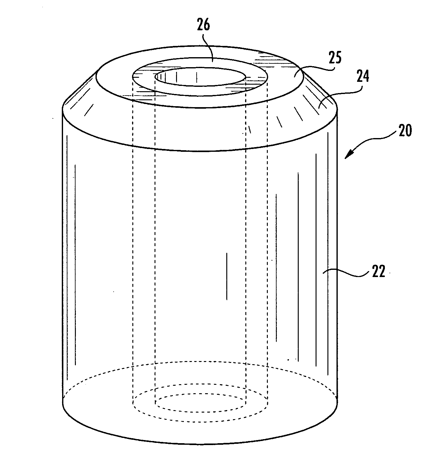
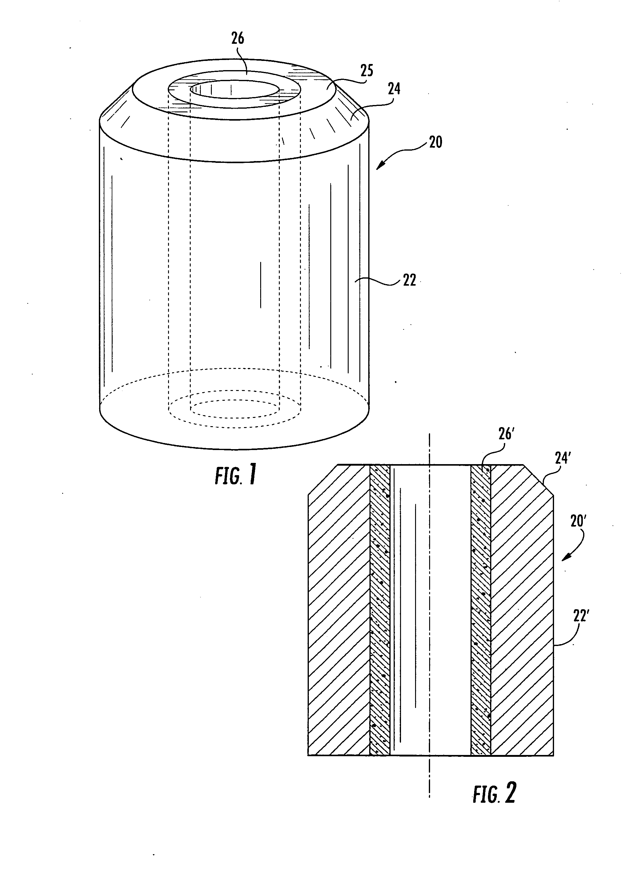
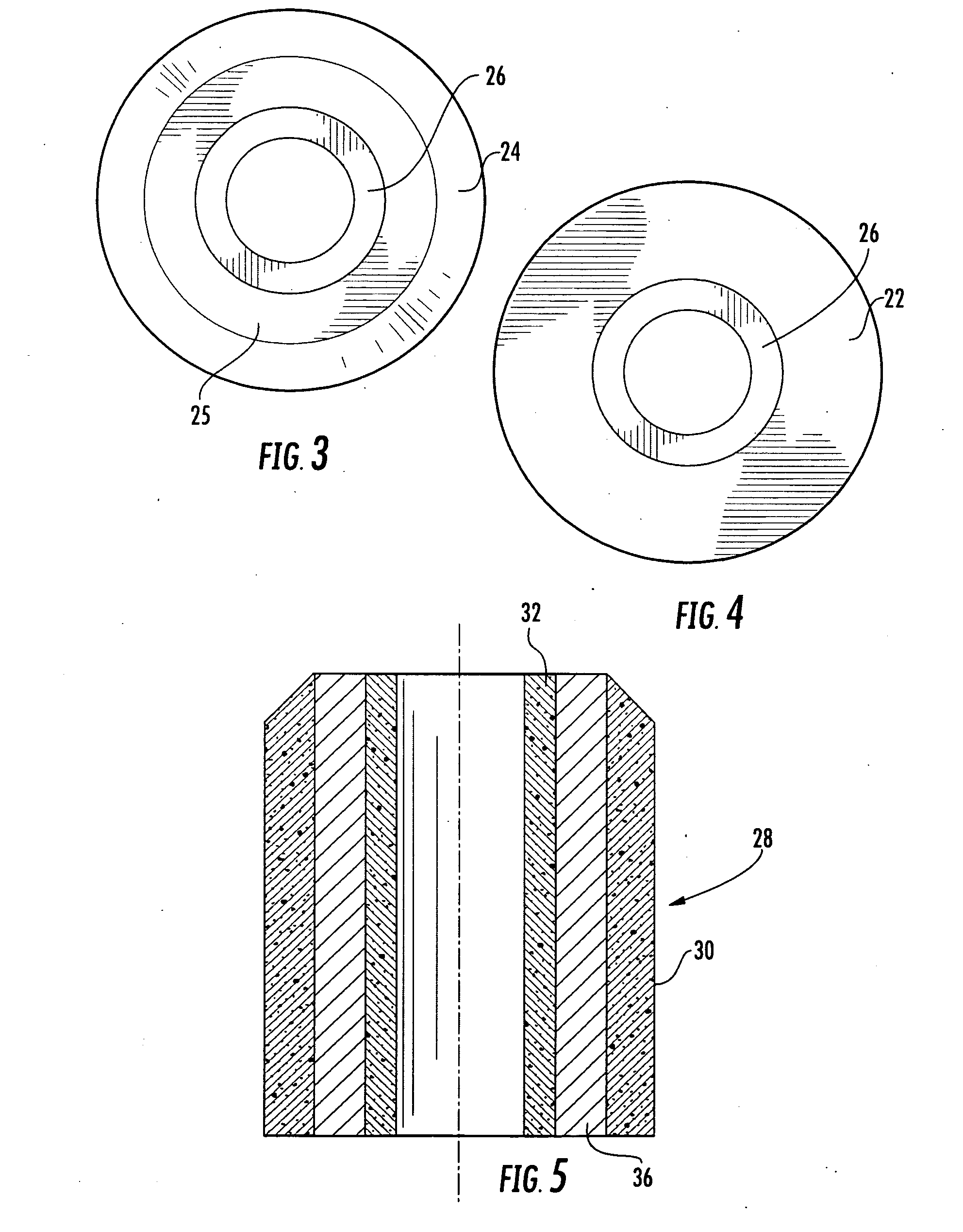
[0038]FIG. 1 shows generally at 20 in a perspective view a representation of a hollow, cylindrical bi-component composite billet of the invention. Billet 20 has an outer surface or sleeve 22 of American Iron and Steel Institute (“AISI”) 8620 steel in wrought condition at full density. The sleeve is tapered at one end to form a conical section 24 for entry into an extruder for plastic deformation (not shown in this view). The conical section is chamfered to a flat top surface 25. ...


PUM

PropertyMeasurementUnit
Lengthaaaaaaaaaa
Lengthaaaaaaaaaa
soaking temperatureaaaaaaaaaa

Abstract

The invention provides clad billet for hot working plastic deformation processes for the production of clad products, including, but not limited to, clad pipe and tubing by extrusion of a hollow, bicomponent composite billet having a fully dense structural component and a partially dense component of a specialty alloy at a fraction of porosity predetermined to provide a flow stress compatible with that of the structural component. The components are diffusion bonded to the predetermined fraction of porosity in the specialty component by application of heat and pressure over time, including by hot isostatically pressing the billet components. Computer modeling techniques can be used to determine processing conditions for obtaining flow stress compatibility.

Description

CROSS-REFERENCE TO RELATED APPLICATIONS[0001]This application claims priority from provisional application Ser. No. 61 / 047,494 filed Apr. 24, 2008 for “Multi-component Pre-form Having Controlled Porosity for Production of Clad Products and Methods for Producing Pre-form and Clad Products” the contents of which is incorporated entirely herein by reference.FIELD OF THE INVENTION[0002]This invention relates to composite preforms, commonly referred to as “billets,” that are used as the input material for producing clad pipe and tubing and other clad products, and to methods for producing these composite performs.BACKGROUND OF THE INVENTION[0003]Alloys commonly used to fabricate pipe or tubing often have the bulk structural properties needed for general applications but may be unsuitable for extended use in connection with highly corrosive or otherwise aggressive fluids, including liquids, gases, and slurries. Other less commonly used alloys may be more resistant to corrosion or wear or ...

Claims


Application Information

Patent Timeline
Patent Type & Authority Applications(United States)
IPC IPC(8): B32B5/18B32B15/00B23K31/12
CPCB21C23/22B21C33/004B22F7/004B22F2998/00B22F2998/10Y10T428/12042B22F5/106B22F7/08B22F3/15B22F3/20
Inventor WARKE, VIRENDRA S.MASHL, STEPHEN J.
Owner BODYCOTE IMT INC
Learn More