Facet joint fixation device

a fixation device and facet technology, applied in the field of orthopedic surgery, can solve the problems of herniation or protrusion of disc pieces, intervertebral discs located in highly mobile regions of the spine, and human spine intervertebral discs are disproportionately prone to degeneration

Active Publication Date: 2009-10-29
SUDDABY LOUBERT
View PDF27 Cites 160 Cited by
  • Summary
  • Abstract
  • Description
  • Claims
  • Application Information

AI Technical Summary

Benefits of technology

[0008]It is a general object of the present invention to provide a facet fixation device that can be utilized either directly in a stand alone facet fusion procedure or as an adjunctive fixator to be utilized when other forms of spinal fusion are employed, e.g., as back up for an anterior fusion. It is also the object of this invention to provide for deployment of the device either radiographically or through endoscopically assisted minimally invasive approaches.

Problems solved by technology

The intervertebral discs of the human spine are prone to degeneration.
In particular, the intervertebral discs located in highly mobile regions of the spine are disproportionately prone to degeneration, primarily due to overt and covert trauma to the tissue that occurs in the course of repetitive activities.
Such trauma tends to disrupt the internal architecture of the disc and leads to bulging, herniation or protrusion of pieces of the disc, and the eventual collapse of the disc space.
The resultant mechanical and / or chemical irritation of the surrounding neural elements, such as the spinal cord and nerves, may cause pain, inflammation and varying degrees of osteoarthritis and disability.
Additionally, the loss of disc space height relaxes tension on the longitudinal spinal ligaments, thereby contributing to varying degrees of spinal instability.
These prior treatments, while fairly adequate for their purpose, suffer from a number of drawbacks.
Operations involving the mechanical fixation with a simple screw are largely adjunctive, that is, the screw alone is not sufficient as a means for fixing the facet joint.

Method used


Image

  • Facet joint fixation device
  • Facet joint fixation device
  • Facet joint fixation device

Examples


first embodiment

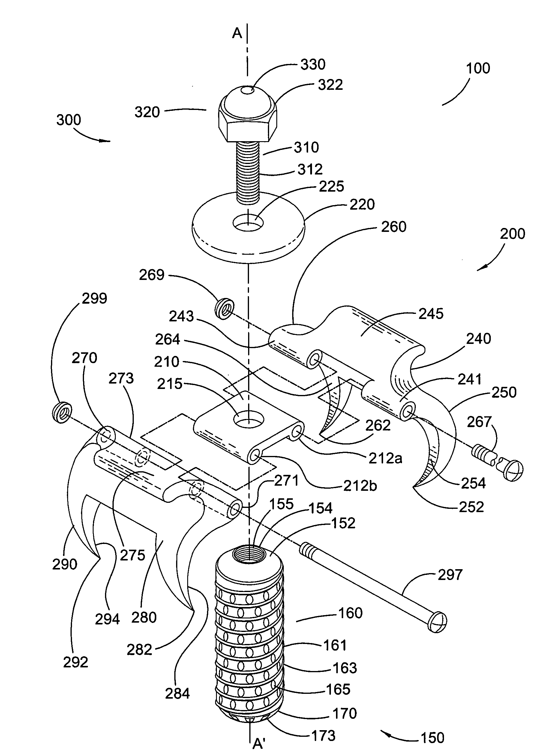
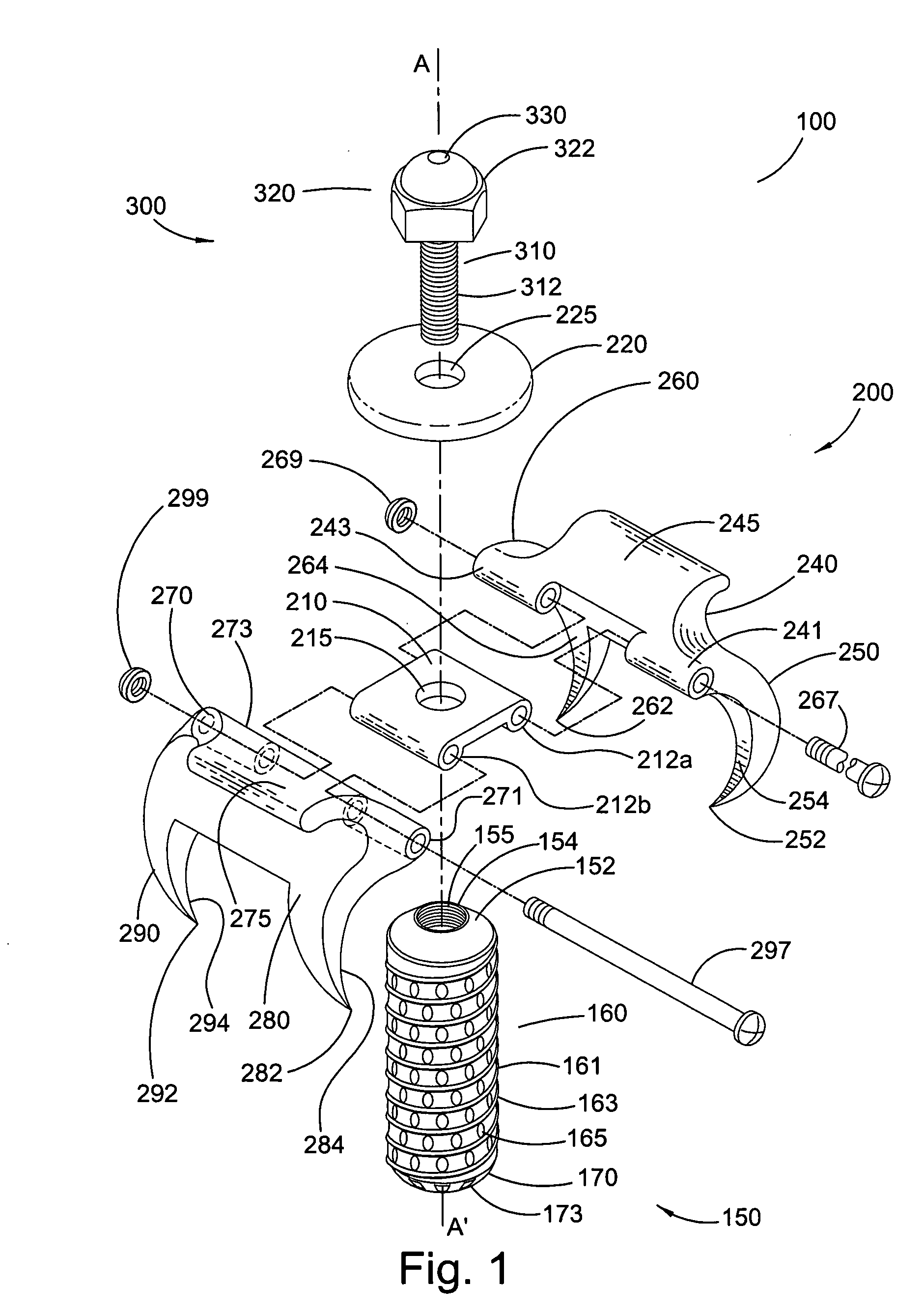
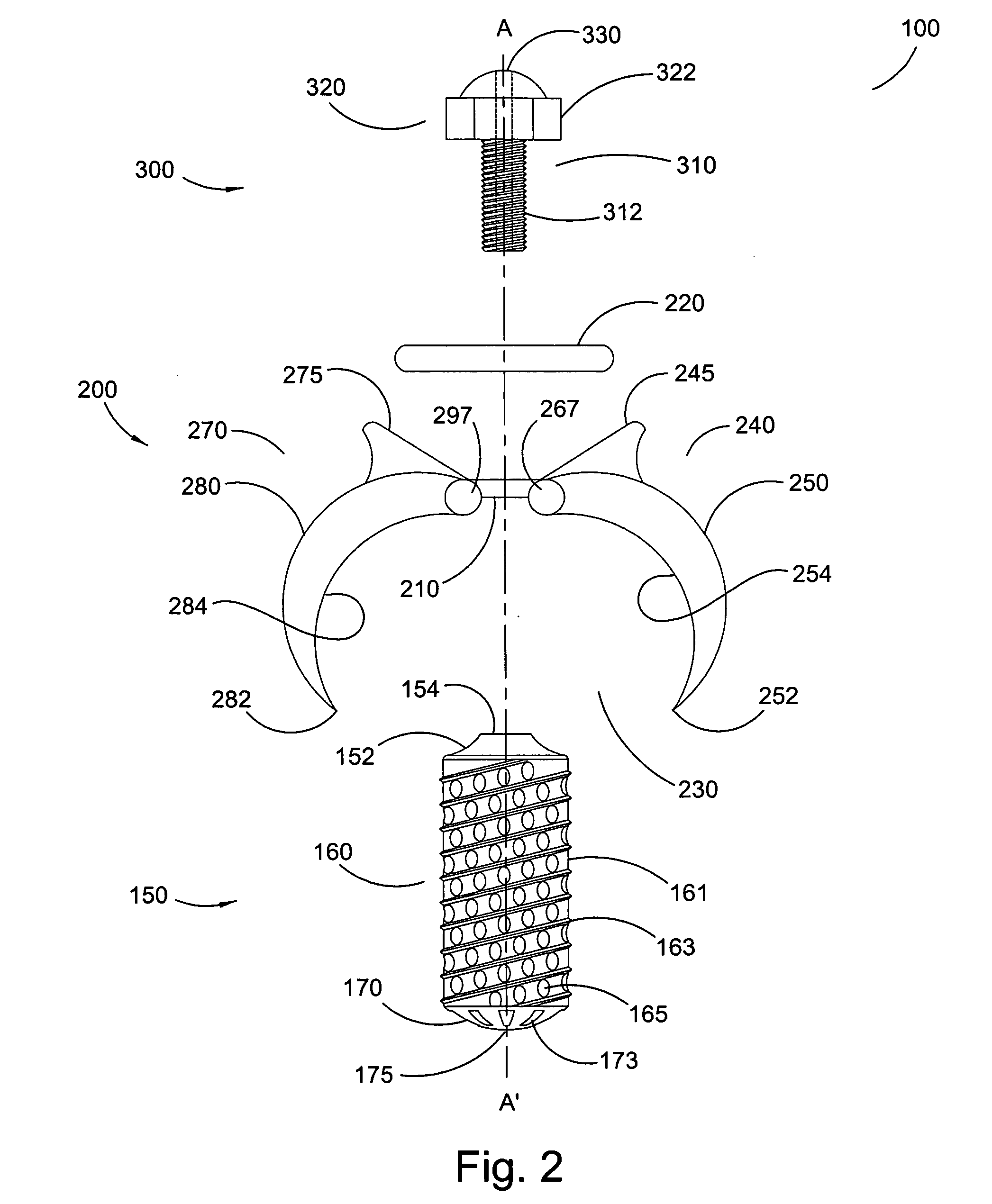
[0048]The first embodiment facet fixation device 100 is best understood in view of FIGS. 1-9g. FIG. 1 is a perspective view of facet fixation device 100 broadly comprising inter-bone implant 150, screw 300, and bone fixation apparatus 200, hereinafter referred to as clamp 200.

[0049]Screw 300, which may be any suitable screw, broadly includes head 320, shaft 310 having threads 312, and, preferably, through-bore 330. The screw drive of screw 300 may be of any type, but is preferably hex cap screw 322 when used in combination with clamp 200. Screw 300 may further include plate 220, the function of which is described in detail infra. Plate 220 may be a separate component, as shown in the figures, or integrally formed with head 320.

[0050]As shown in FIGS. 3-5, inter-bone implant 150 comprises body 160, which is preferably hollow and either cylindrical or frustoconical, first end 152, and second end 170. First end 152 includes aperture 154 having internal threads 155, which are operativel...

second embodiment

[0068]The second embodiment facet fixation device 100, is best understood in view of FIGS. 10-14h. FIG. 10 is a perspective view of device 100 broadly comprising inter-bone implant 150, screw 300, and bone fixation apparatus 400, hereinafter referred to as cap 400.

[0069]Screw 300, which may be any suitable screw, broadly includes head 320, shaft 310 having threads 312, and, preferably, through-bore 330, as shown in FIGS. 11 and 12. The screw drive of screw 300 may be of any type, but is preferably cruciform screw drive 324 when used in combination with cap 400.

[0070]As in the first embodiment, inter-bone implant 150 includes body 160, which is preferably hollow and either cylindrical or frustoconical, first end 152, and second end 170. First end 152 includes aperture 154 having internal threads 155, which are operatively arranged to threadingly engage threads 312 of screw 300. Second end 170 preferably includes one or more apertures 173, which are arranged to accept residual bone ma...


PUM


Abstract

A device for fixing the positions of proximate bone elements including an inter-bone implant adapted to be implanted between suitably prepared proximate bone elements, the inter-bone implant having an internally threaded aperture, a bone fixation apparatus including a base having an eyelet and a means connected to the base for mechanically fixing the positions of the proximate bone elements relative to each other, the eyelet being substantially aligned with the internally threaded aperture, and a screw having a head and a threaded shaft extending therefrom, wherein the shaft is operatively arranged to extend through the eyelet and threadingly engage the internally threaded aperture, and the screw is operatively arranged to secure the bone fixation apparatus to the inter-bone implant.

Description

FIELD OF THE INVENTION[0001]This invention relates to the field of orthopedic surgery and, particularly, to inter-bone fixation and fusion devices and, even more particularly, to interarticular facet joint fixation and fusion devices.BACKGROUND OF THE INVENTION[0002]The intervertebral discs of the human spine are prone to degeneration. In particular, the intervertebral discs located in highly mobile regions of the spine are disproportionately prone to degeneration, primarily due to overt and covert trauma to the tissue that occurs in the course of repetitive activities. Such trauma tends to disrupt the internal architecture of the disc and leads to bulging, herniation or protrusion of pieces of the disc, and the eventual collapse of the disc space. The resultant mechanical and / or chemical irritation of the surrounding neural elements, such as the spinal cord and nerves, may cause pain, inflammation and varying degrees of osteoarthritis and disability. Additionally, the loss of disc ...

Claims


Application Information

Patent Timeline
Patent Type & Authority Applications(United States)
IPC IPC(8): A61B17/04A61B17/70
CPCA61B17/1637A61B17/1655A61B2217/005A61B17/7064A61B17/1671
Inventor SUDDABY, LOUBERT
Owner SUDDABY LOUBERT
Why Eureka
Try Eureka