
Manually Operable Drain Device

a man-operated, drain device technology, applied in water installations, washstands, constructions, etc., can solve problems such as difficulty or inability to meet, complex apparatus, and difficulty in providing various man-operated drain strainers,

Inactive Publication Date: 2009-11-05
DYNAMIC DRAIN SOLUTIONS
View PDF9 Cites 10 Cited by
  • Summary
  • Abstract
  • Description
  • Claims
  • Application Information

AI Technical Summary

Benefits of technology

[0032]In a still further preferred embodiment, the method includes the step of gripping a strand of waste material at a plurality of places along the strand and thereafter forcing respective parts of the strand simultaneously into apart-spaced openings in a bottom member of the manually operable device, thereby elongating the strand sufficiently to cause it to break into a plurality of shorter pieces.

Problems solved by technology

However, in order for such devices to perform satisfactorily, they must be regularly cleaned, because they are prone to clogging.
These devices are usually electrically powered “garbage disposals” that have little need for manual cleaning and operation, although they require significant space for installation, electrical power for operation, and adequate access for maintenance.
These requirements are difficult or impossible to meet in the typical shower, tub, or sink outside the kitchen area.
Previous attempts to provide various manually operable drain strainers, waste traps, and comminuting devices, including comminuting or shearing devices designed to cut human hair, have various limitations.
For example, Gandillon, U.S. Pat. No. 1,614,358, describes a manually operated device fitted under a common sink outlet, but the apparatus is prone to clogging, complex, and undesirably large.
Furthermore, the device is prone to foriling with hair.
The device requires significant space for installation and maintenance and has a vertically oriented shaft that is prone to fouling with hair.
The device does not allow for manual operation when water flow provides insufficient power.
However, the central shaft is exposed to solid waste entering the drain, and is, therefore, prone to fouling.
However, the device is actuated by linear strokes of a steeply pitched threaded rod passing through a threaded bore of a rotor, and the threaded rod is exposed to solid waste material and is therefore prone to fouling.
Other devices, such as electric razors that are designed specifically to cut hair, are not easily adapted for use in handling hair caught on sink, tub, or shower drain parts to prevent Clogging of those drains.
Ochiai et al., U.S. Pat. No. 4,549,352, and Szymansky, U.S. Pat. No. 5,901,446, describe cutting devices used in common electric shavers, but hair that has caught in sink, tub, or shower drains tends to be unlikely to be oriented so that these devices would be effective.
However, hair trapped in the device is not perpendicularly oriented to the shearing surface.
This dramatically decreases the efficacy of any shearing device as significant portion of the captured hair has a tendency to bind such a mechanism if not held perpendicular to the shearing motion.
The need for precisely machined and aligned shearing surfaces makes application to a legacy drain's cross members extremely difficult to achieve.
This is especially true given the lack of standardization of the cross members.
Also, the use of such drain orifice cross members as strainer arms is not effective at catching a majority of hairs flowing into the orifice.
Materials and manufacturing costs are significant concerns of manufacturers in the plumbing field, thereby decreasing the likelihood that such a device would ever be cost effective enough to see market implementation.
Use of shearing blades increases the costs beyond those in tuned with the alignment and precision issues as they require use of corrosion resistant materials, most likely ceramics, stainless steel, or other corrosion resistant yet durable alloys, with the concomitant cost issues associated with such materials.
While mention is briefly made regarding use of plastics in this capacity, it is apparent to one skilled in the art of rending hair with a bladed instrument that plastic is not an effective alternative.

Method used


Image

  • Manually Operable Drain Device
  • Manually Operable Drain Device
  • Manually Operable Drain Device

Examples


Embodiment Construction

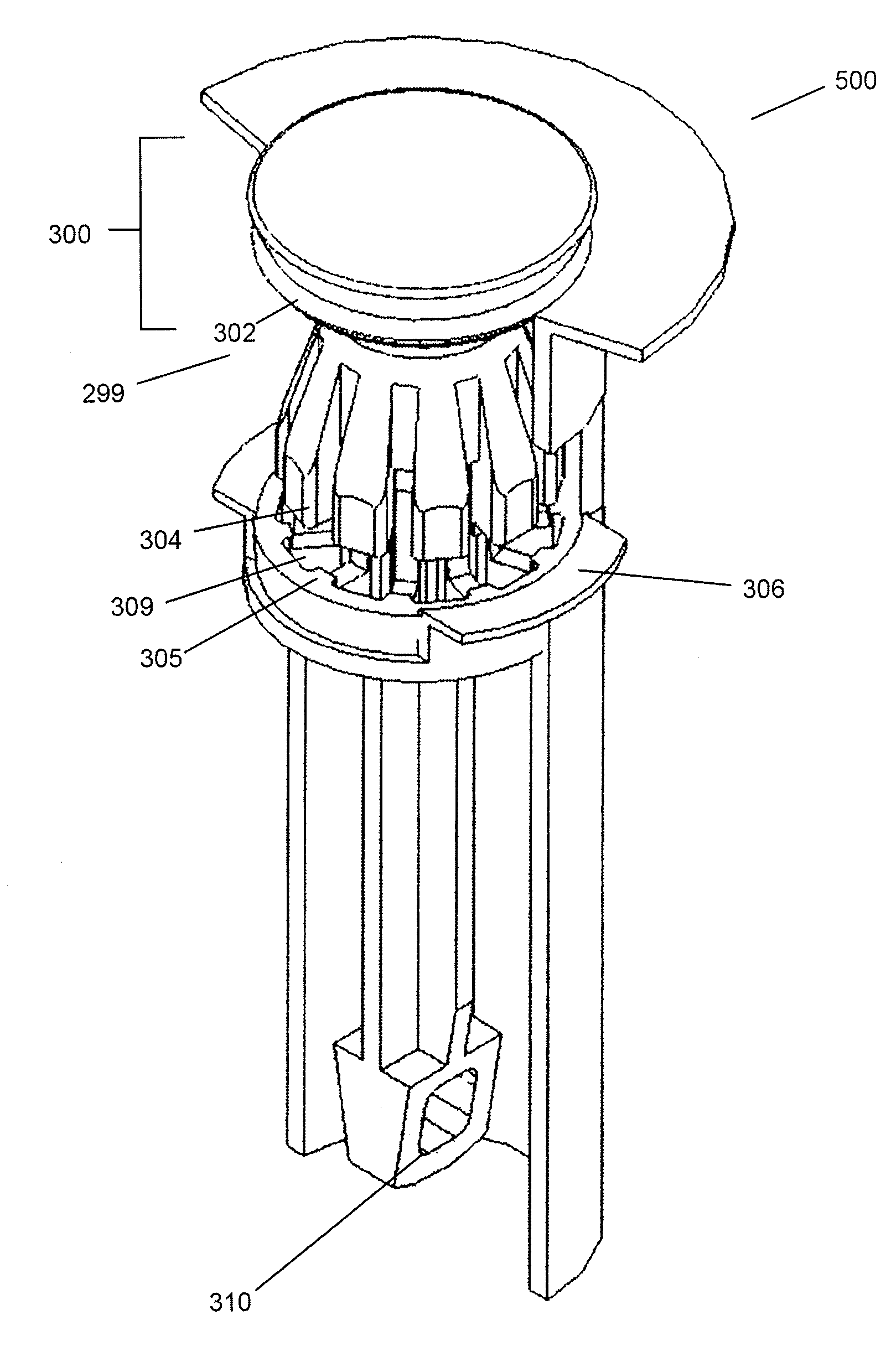
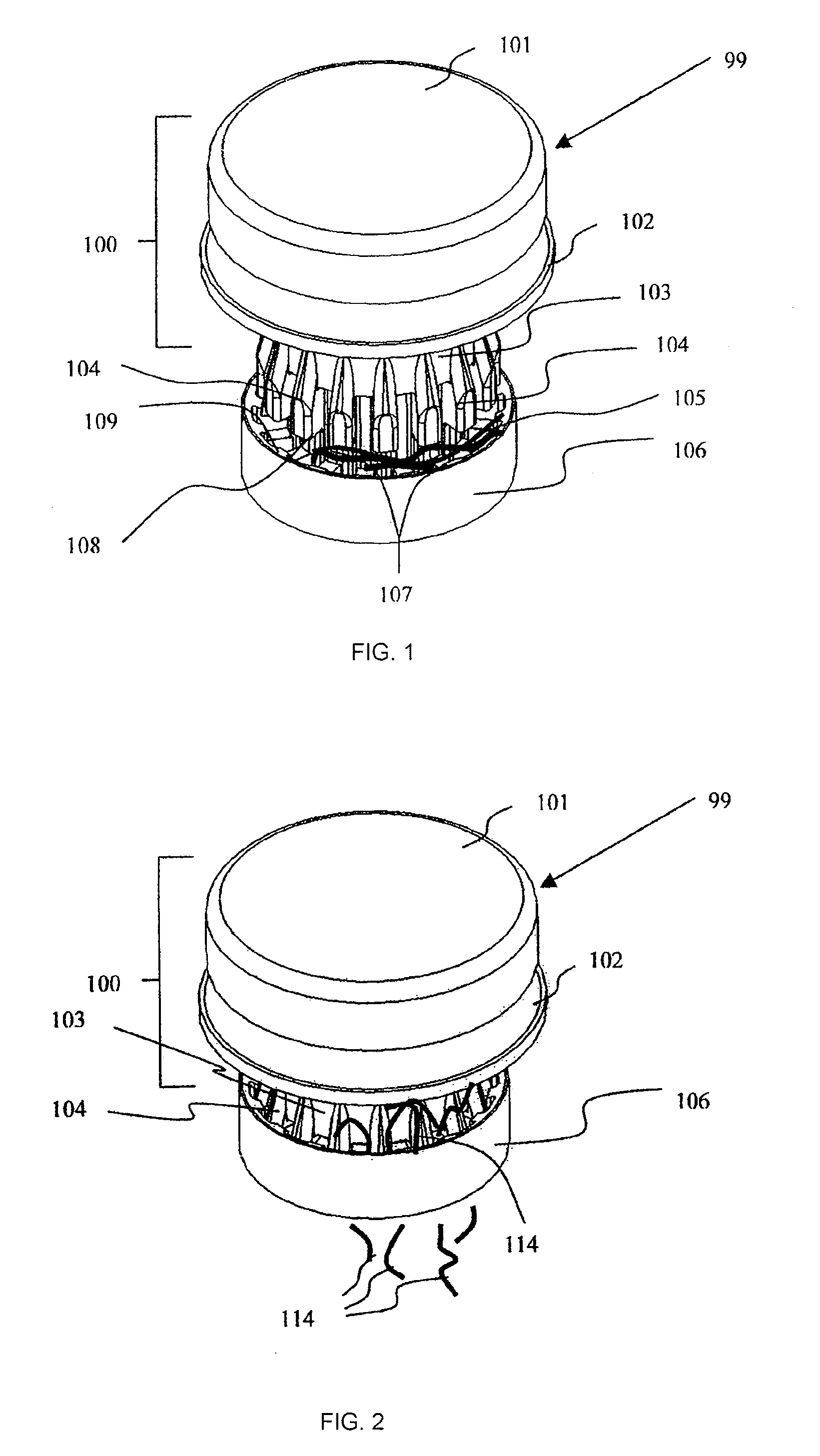
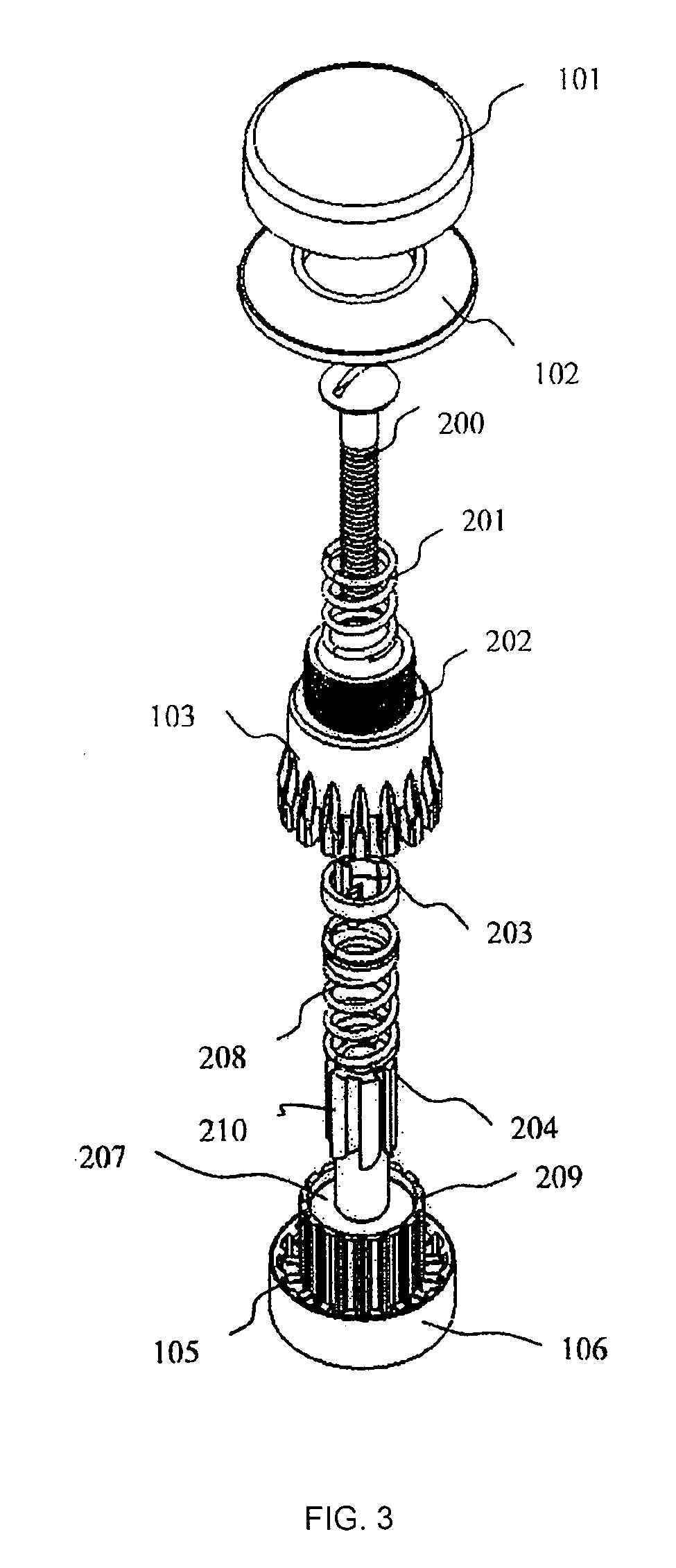
[0042]Referring first to FIGS. 1-4, a manually operable dram mounted device 99 shown assembled in FIG. 1 may be installed in an open drain receptacle (as typified in FIG. 13 and seen in sink, bathtub, or shower drains) (add picture of common drain receptacle and label it FIG. 13) for disposal of solid materials commonly encountered in a household or office, other than in a kitchen, such as hair, thread, fingernails, soapy residues, and so forth.

[0043]Referring to FIG. 1, the device 99 is in a ready condition, before operation, fitted for a typical drain receptacle. The device 99 may be manufactured in a size appropriate to fit snugly within the receptacle of a conventional drain for a tub, shower, or sink, in which the receptacle portion includes a horizontal bottom support cross member defining a threaded hole centered within the strainer bottom.

[0044]The device 99 includes a perforated strainer and ripping cutting plate 106 which is stationary and may be supported by a small dista...


PUM


Abstract

A method for preventing waste materials from clogging a household drain, the method comprising: a) receiving a quantity of waste material contained in a flow of liquid toward a drain receptacle; b) guiding the flow of liquid to a predetermined position adjacent a part of a manually operable device mounted within the drain receptacle and gathering the quantity of the waste material from the flow of liquid in a first location adjacent a member of the manually operable device located in the drain receptacle; c) maintaining the quantity of waste material generally perpendicular to the vertical motion of a manually moving size reduction assembly; d) manually moving the size reduction assembly portion of the device so as to subject the quantity of waste material to abrading action, thereby producing an abraded portion of waste material as a plurality of smaller pieces; and e) carrying the abraded pieces away from the drain receptacle and through a drain conduit in the flow of water.

Description

REFERENCE TO RELATED APPLICATIONS [0001]This application claims the benefit of U.S. Provisional Patent Applications Nos. 60 / 814,409, filed Jun. 15, 2006; 60 / 814,495, filed Jun. 15, 2006; 60 / 814,497, filed Jun. 15, 2006; 60 / 855,577, filed Oct. 30, 2006; 60 / 873,657, filed Dec. 8, 2006; and U.S. Patent Publication No. 2007 / 0290082, filed May 4, 2007; the complete disclosure of each of which are incorporated herein, in the entirety.BACKGROUND OF THE INVENTION [0002]1. Field of the Invention[0003]The present invention relates to a device for handling solid materials, such as hair, to reduce clogging of household sink, tub, and shower drains. More particularly, the present invention relates to a manually operable device for reducing the size of pieces of hair and other solid waste materials to smaller pieces less likely to accumulate and clog a drain.[0004]2. Description of Related Art[0005]Drain receptacles for sinks, showers, and bath tubs frequently have strainers and filters covering ...

Claims


Application Information

Patent Timeline
Patent Type & Authority Applications(United States)
IPC IPC(8): A47K1/14
CPCE03C1/262
Inventor SCORVO, SEAN
Owner DYNAMIC DRAIN SOLUTIONS
Learn More