
Motion translation mechanism

Active Publication Date: 2009-11-05
EFFICIENT V
View PDF47 Cites 52 Cited by
  • Summary
  • Abstract
  • Description
  • Claims
  • Application Information

AI Technical Summary

Benefits of technology

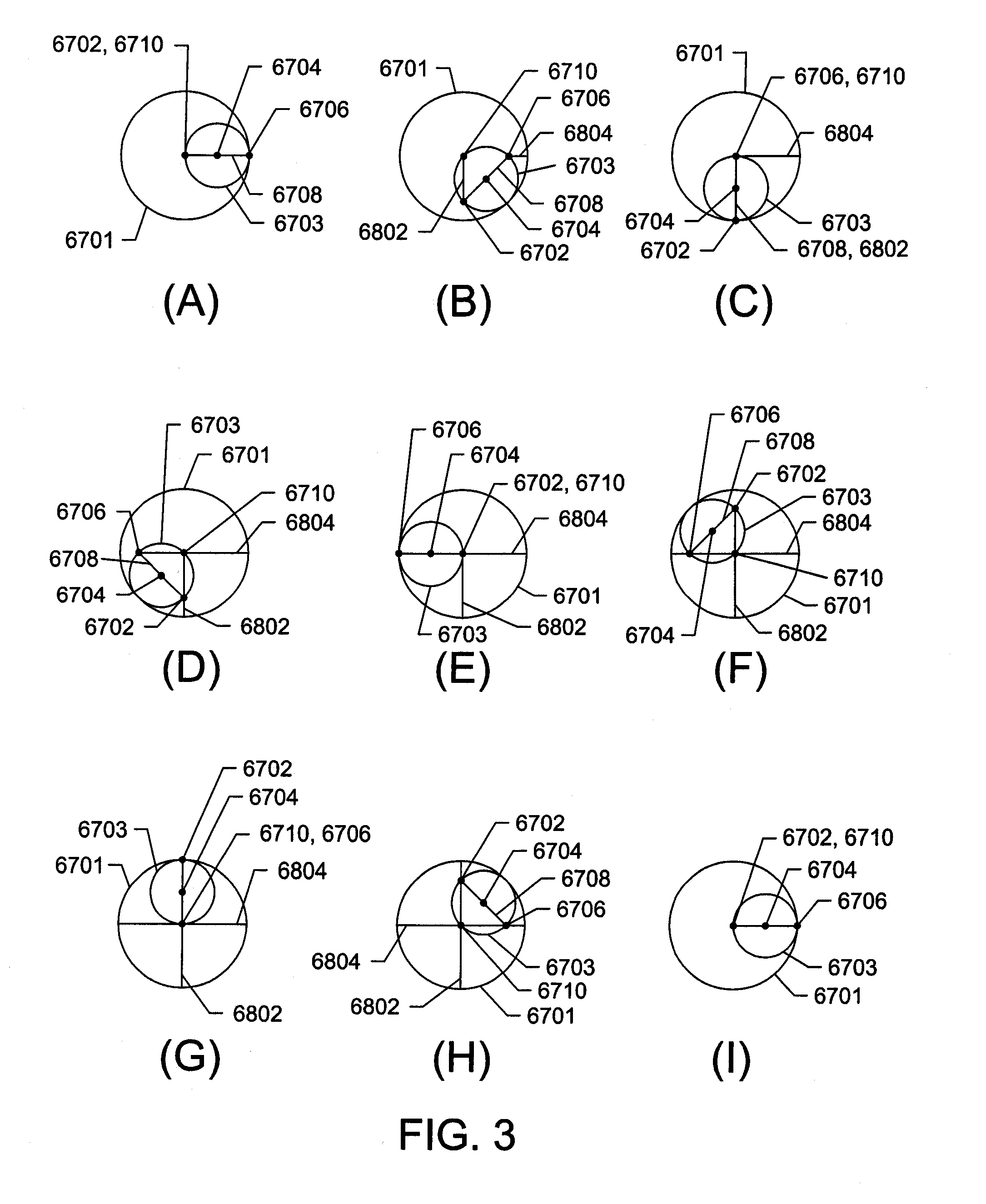
[0024]In some embodiments, the elongate body is fixedly attached to the piston head. The width of the elongate body can be substantially uniform over the length of the body between the piston head and the crankshaft-bearing-region. In other embodiments, the width of the elongate body can be less than the piston head and / or spaced from a corresponding wall of a crankcase or cylinder, e.g., to reduce friction. When the drive-member is engaged with the crankshaft-drive, a moment applied to the drive-member can urge a region of the crankshaft along a hypocycloidal path.
[0038]A moment applied to the drive-member can urge the crankshaft-drive to orbit the central-axis-of-rotation, thereby urging the first and second pistons to reciprocate along respective substantially linear strokes in the respective first and second cylinder-bores.

Problems solved by technology

Consequently, longer connecting rods usually impart lower wear rates to slider and pivoting connections.

Method used


Image

  • Motion translation mechanism
  • Motion translation mechanism
  • Motion translation mechanism

Examples


first exemplary embodiment

Overview of Reciprocating Piston Machines and a First Exemplary Embodiment

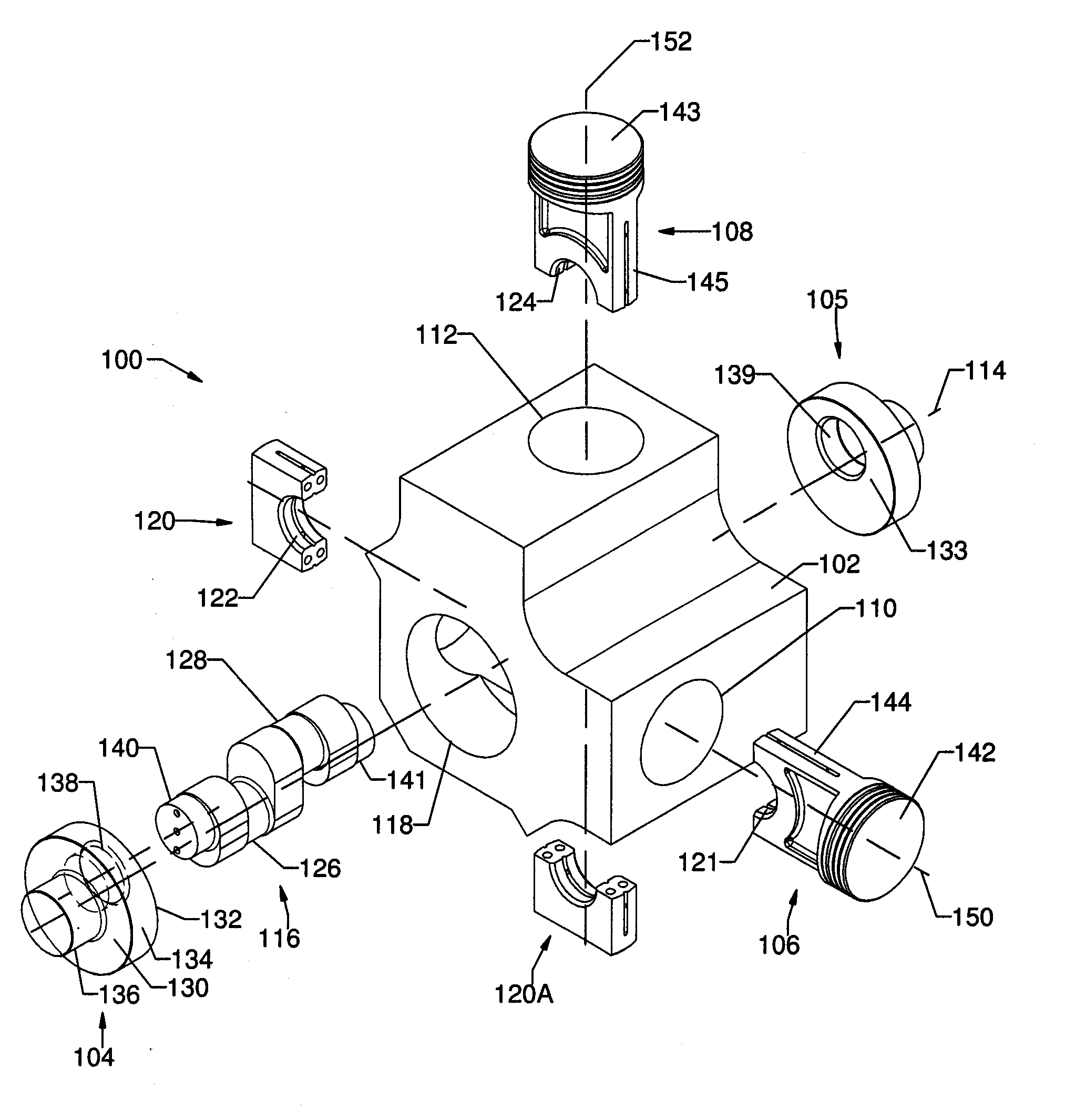
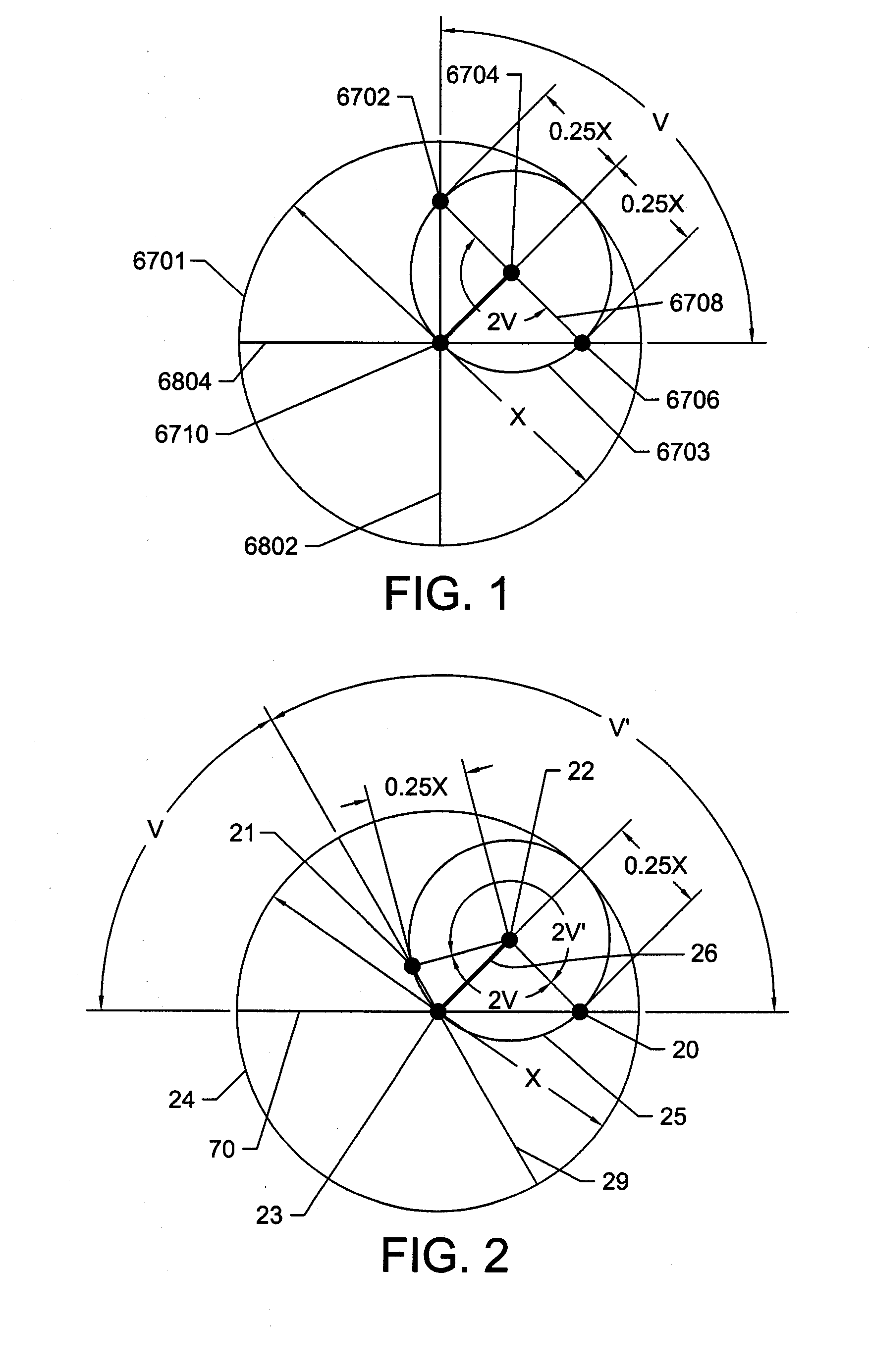
[0177]FIG. 7 illustrates an exploded view of one exemplary embodiment of a reciprocating piston machine incorporating MTM architecture. As shown, the piston-cylinders 610 and 612 of the cylinder block 602 are angularly displaced relative to the central axis of the crankcase 618 by an angle V measuring approximately 45-degrees. The planetary crankshaft 616 comprises crankpins 626, 628 being angularly offset relative to the crankshaft drives 640, 641 by an angle 2V measuring approximately 90-degrees.

[0178]The pistons 606 and 608 respectively comprise piston heads 642 and 643, piston-ring receiving regions 609 and 609A, and elongate bodies 644 and 645 being narrower than a major diameter of the respective piston-ring receiving region. The proximal end of each elongate body 644, 645 defines a respective recessed region 621, 624. Each end-cap 620, 620A (also referred to herein as a “bearing cap”) defines a respecti...

second exemplary embodiment

[0188]Additional features of pistons, crankshafts, drive-members and blocks are described with reference to FIGS. 1-6, 8A-8D, and 38.

[0189]FIGS. 8A and 8B illustrate an alternative embodiment of a motion translation mechanism 10 incorporating MTM architecture. In this alternative embodiment, the planetary crankshaft 9 (shown in FIGS. 8C and 8D) includes one or more pinions 8 for rotatably engaging a ring gear 7, as described above. The longitudinal axes 14, 15 of the piston journals 12, 13 radially spaced from the crankshaft-drive axis-of-rotation 17 and angularly offset from each other by an angle 2V.

[0190]Although the illustrated crankshaft 9 includes pinions 8 positioned adjacent the crankshaft drive 16, the pinions 8 can be located at various other locations along the crankshaft 9. The crankshaft drive 16 can be configured as described herein.

[0191]In some embodiments, the radius of the pinion 8 (e.g., a circular pitch radius) is substantially equal to the radial spacing from th...


PUM


Abstract

This disclosure concerns machines that convert rotating motion to reciprocation, and vice-versa, and more particularly, but not exclusively, to reciprocating piston machines. Some embodiments include a crankshaft defining a crankshaft-drive and at least one radially extending piston-journal spaced from the crankshaft-drive, and a piston configured to pivotally engage the piston-journal. The piston defines a cylindrical head and an elongate body. Some embodiments further include a drive-member defining a central-axis-of-rotation and being rotatably engageable with the crankshaft-drive. Some embodiments also include a block defining one or more cylinders for receiving one or more pistons. The drive-member rotates when the piston reciprocates, and vice-versa.

Description

CROSS REFERENCE TO RELATED APPLICATIONS[0001]This application claims priority benefit of and is a continuation-in-part of copending international patent application PCT / US2008 / 000167, filed on Jan. 4, 2008, and designating the U.S., which international patent application claims priority to U.S. Provisional Patent Application No. 60 / 878,752, filed on Jan. 5, 2007, and of copending international patent application PCT / US2009 / 038133, filed on Mar. 24, 2009, and designating the U.S., which international patent application claims priority to U.S. Provisional Patent Application No. 61 / 070,621, filed on Mar. 24, 2008. These applications are incorporated herein by reference.FIELD[0002]This application concerns machines that convert rotating motion to reciprocating motion, and vice-versa, and more particularly, but not exclusively, to reciprocating piston machines.BACKGROUND[0003]Reciprocating piston machines have been used to convert reciprocating motion to rotating motion, and vice-versa, ...

Claims


Application Information

Patent Timeline
IPC IPC(8): F01B9/02F16H21/00F16J10/00F16J1/08F04B19/00F02F1/00
CPCF02B75/32F16H21/36Y10T74/18248Y10T74/18272Y10T74/18184F02B75/22
Inventor COOK, CHRISTOPHER L.COOK, SCOTT
Owner EFFICIENT V
Learn More