Earthing system for a wind turbine connected to a utility grid and for a wind turbine park

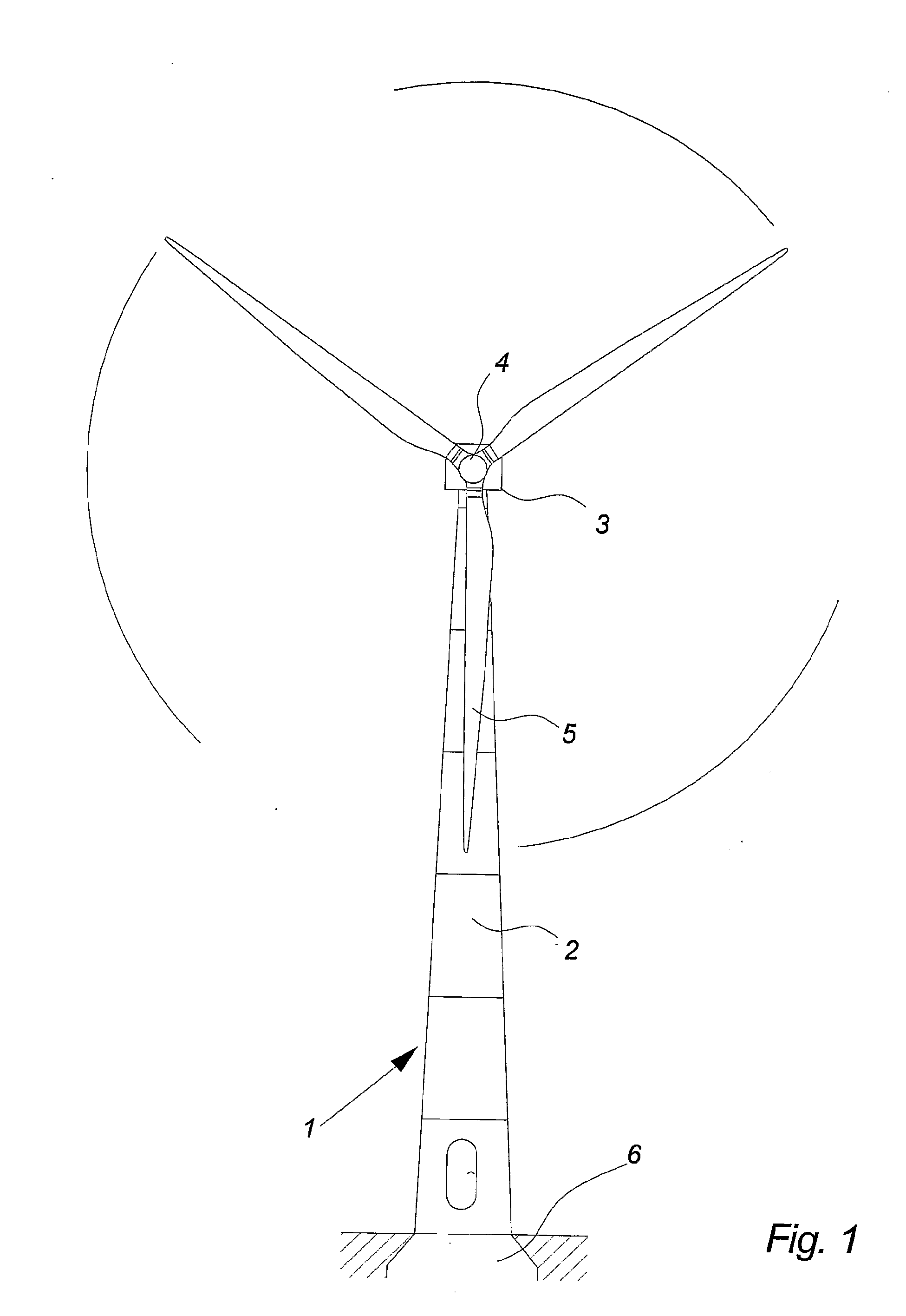
a technology for wind turbines and earth connections, which is applied to wind motor supports/mounts, non-positive displacement fluid engines, liquid fuel engine components, etc., can solve the problems of reducing the quality of the power produced, affecting the service life of the wind turbine, etc., to achieve efficient and secure connection, secure and efficient earth connection, and simple

Active Publication Date: 2009-11-05
VESTAS WIND SYST AS
View PDF4 Cites 10 Cited by
  • Summary
  • Abstract
  • Description
  • Claims
  • Application Information

AI Technical Summary

Benefits of technology

[0043]Using the wind turbine foundation is a simple, secure and efficient way to establish an earth connection and by supplementing this by means of electric conducting means extending substantially horizontally from said wind turbine in the ground a particularly secure and efficient earth connection is established, which is distributed over a large area surrounding the wind turbine.
[0044]By bringing the different earthing systems together in one defined place in the wind turbine it is possible to make a efficient and secure connection to the electric systems, hereby eliminating or reducing the risk of dangerous or damaging potential differences occurring in the or around the wind turbine.

Problems solved by technology

Overvoltage caused by a fault situation such as a short circuit, lightening strike or other can be potentially very damaging for the wind turbine, possible personnel operating it or at least it can reduce the quality of the power produced.
The problem with this type of earthing system is that the quality and the stability of the earth connection can be difficult to maintain, in that it can be difficult to ensure that all parts of the wind turbine is securely grounded at all times and that no potentially damaging or dangerous electrical potential differences occur inside or around the wind turbine.

Method used


Image

  • Earthing system for a wind turbine connected to a utility grid and for a wind turbine park
  • Earthing system for a wind turbine connected to a utility grid and for a wind turbine park
  • Earthing system for a wind turbine connected to a utility grid and for a wind turbine park

Examples


first embodiment

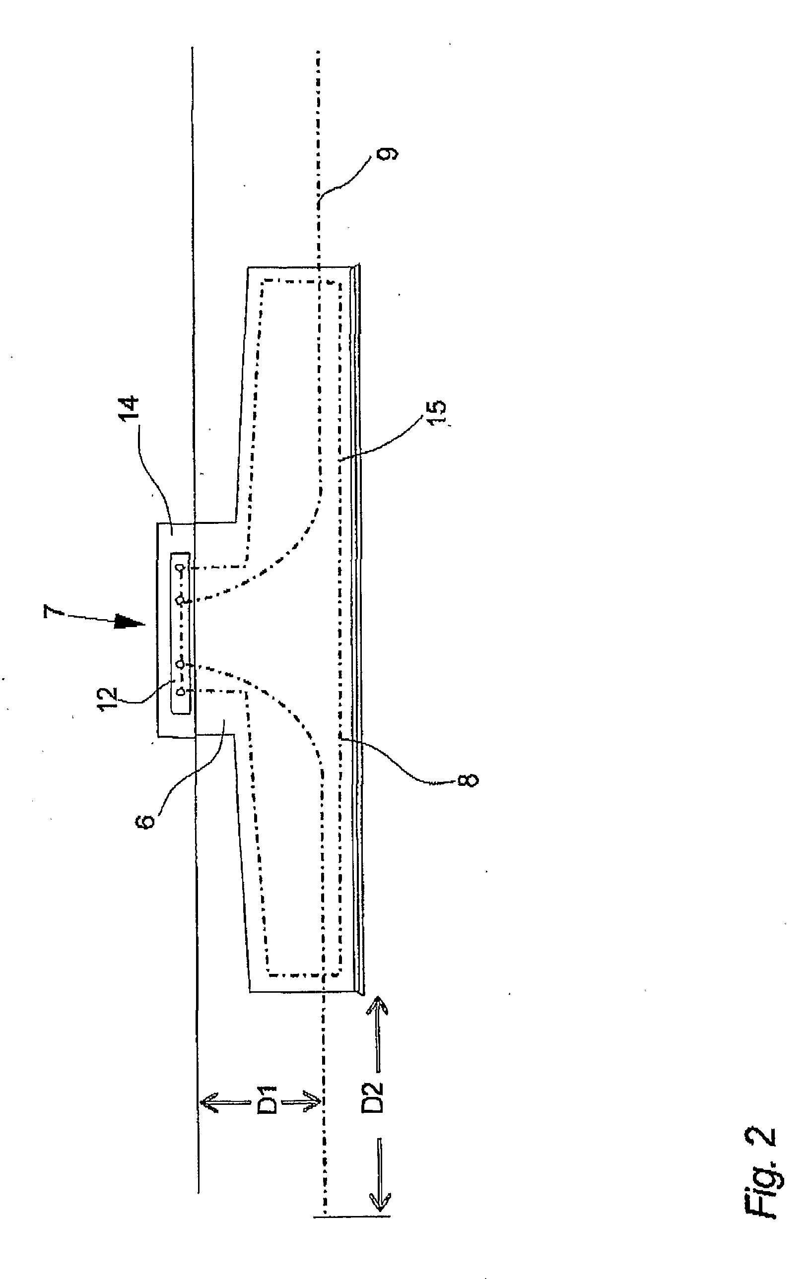
[0094]FIG. 5 illustrates a cross section a wind turbine tower 2 comprising a rail 12, as seen from the top.

[0095]In this embodiment of the invention the rail 12 is welded directly to the inside surface of the foundation section 14, but in another embodiment the rail 12 could also be bolted to the foundation section 14 or if the foundation does not comprise a foundation section 14, the rail 12 could be mounted on the bottom of the tower 2 immediately above the foundation 6. No matter the design or type of the tower 2 or the foundation 6 it is an object of the invention to establish a connection between all power and / or signal conducting cables 16, 18, 19 to an electrically earth potential in form of the rail 12 in one defined place within the wind turbine 1.

[0096]Protective measures against injuries of living beings due to touch voltage are reduced to a tolerable level by the design of the down conductor of the wind turbine 1. In this embodiment the down conductor of the lightning pr...

second embodiment

[0105]FIG. 6 illustrates a cross section a wind turbine tower 2 comprising a rail 12, as seen from the top.

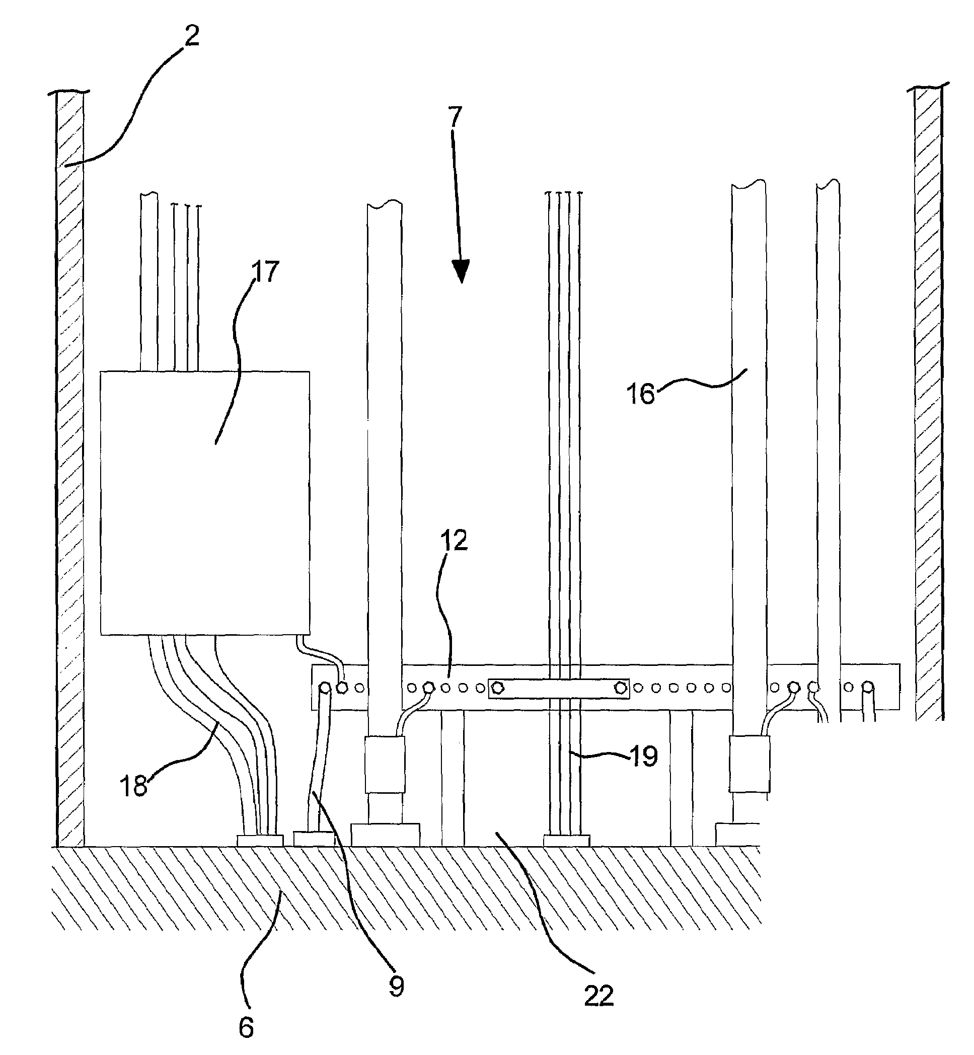
[0106]In this embodiment of the invention the 12 all the power and / or signal conducting cables 16, 18, 19 and cables from all earthing systems 7, 8, 9, 11 are all connected in one defined area via the rail 12 at the bottom of the tower 2. The rail 12 is then further connected to the tower 2 by means of a earth cable 20 which thereby further establishes a direct or indirect current conducting connection between the earthing system 7 and all connected metal parts of the wind turbine 1.

[0107]FIG. 7 illustrates a cross section a wind turbine tower 2 comprising a rail 12, as seen from the front.

[0108]In this embodiment all cables and wires are connected to the earthing system 7 at the single point of entry (SPE) 22 which in this case is the place just above the ground level at the bottom of the wind turbine tower 2 where all wires and cables enters or exits the wind turbine 1 throug...


PUM


Abstract

The invention relates to an earthing system for a wind turbine connected to a utility grid. The wind turbine comprises at least one electric system such as low or high voltage power systems and cables (16), at least one control system such as a SCADA system and control cables (18), and/or at least one safety system such as a lightning protection system, wherein a connection to an electrically earth potential is established from one defined place (12) within the wind turbine for said systems. In another embodiment, a wind turbine comprises at least two electric systems such as a lightning protection system and a low or high voltage power system, an electrically earth potential established by at least one foundation earthing (8) including at least one earthing wire embedded partly or totally in the wind turbine foundation (6), and at least one electric conducting means (9) extending radial from said wind turbine (1) into the ground, wherein a connection to said electrically earth potential is established from one defined place within the wind turbine (1) for said systems. Even further the invention relates to an earthing system

Description

BACKGROUND OF THE INVENTION [0001]The invention relates to a wind turbine connected to a utility grid and a wind turbine park.DESCRIPTION OF THE RELATED ART [0002]A wind turbine known in the art comprises a tapered wind turbine tower and a wind turbine nacelle positioned on top of the tower. A wind turbine rotor with a number of wind turbine blades is connected to the nacelle through a low speed shaft, which extends out of the nacelle front as illustrated on FIG. 1.[0003]Overvoltage caused by a fault situation such as a short circuit, lightening strike or other can be potentially very damaging for the wind turbine, possible personnel operating it or at least it can reduce the quality of the power produced. It is therefore known to provide the wind turbine with some sort of earthing system.[0004]In U.S. Pat. No. 6,932,574 B2 is shown a wind turbine comprising a lightning protection system and a system for continuously discharging of electrostatic charges of the wind turbine blades. T...

Claims


Application Information

Patent Timeline
Patent Type & Authority Applications(United States)
IPC IPC(8): H02G13/00F03D11/00F03D9/00
CPCF03D9/003F03D9/005F03D11/00F03D11/0033H02G13/40H02G13/00Y02E10/728H02G13/80F03D11/045F03D9/255F03D9/257F03D13/22F03D80/00F03D80/30F03D80/82Y02E10/72
Inventor MOGENSEN, NIELS BIRCHBERTELSEN, KIM
Owner VESTAS WIND SYST AS
Why Eureka
Try Eureka