
Method and system for equalizing a loudspeaker in a room

a loudspeaker and room technology, applied in the field of audio and sound reproduction equipment, can solve the problems of reducing affecting so as to improve the perceived sound quality, improve the sound reproduction quality, and achieve the effect of high probability of a successful resul

Active Publication Date: 2009-11-05
SL AUDIO
View PDF4 Cites 14 Cited by
  • Summary
  • Abstract
  • Description
  • Claims
  • Application Information

AI Technical Summary

Benefits of technology

[0006]It is an object of the present invention to provide a method and a system for equalizing a loudspeaker in order to compensate for an influence of the room in which it is positioned, so as to improve a perceived sound reproduction quality for a person listening to the loudspeaker at a listening position in the room. Still, the method should provide an equalizing of the loudspeaker so that sound reproduction quality is improved also for listeners outside the listening position. The method must be suited for an automatic filter design with only very limited tasks required for a non-skilled operator with a high probability of a successful result. Hereby, the method is suited for use in a hi-fi system to be operated by a normal non-skilled person to equalize a hi-fi loudspeaker to a specific position in a living room while still taking into account individual acoustic properties of the room and its interaction with the loudspeaker.
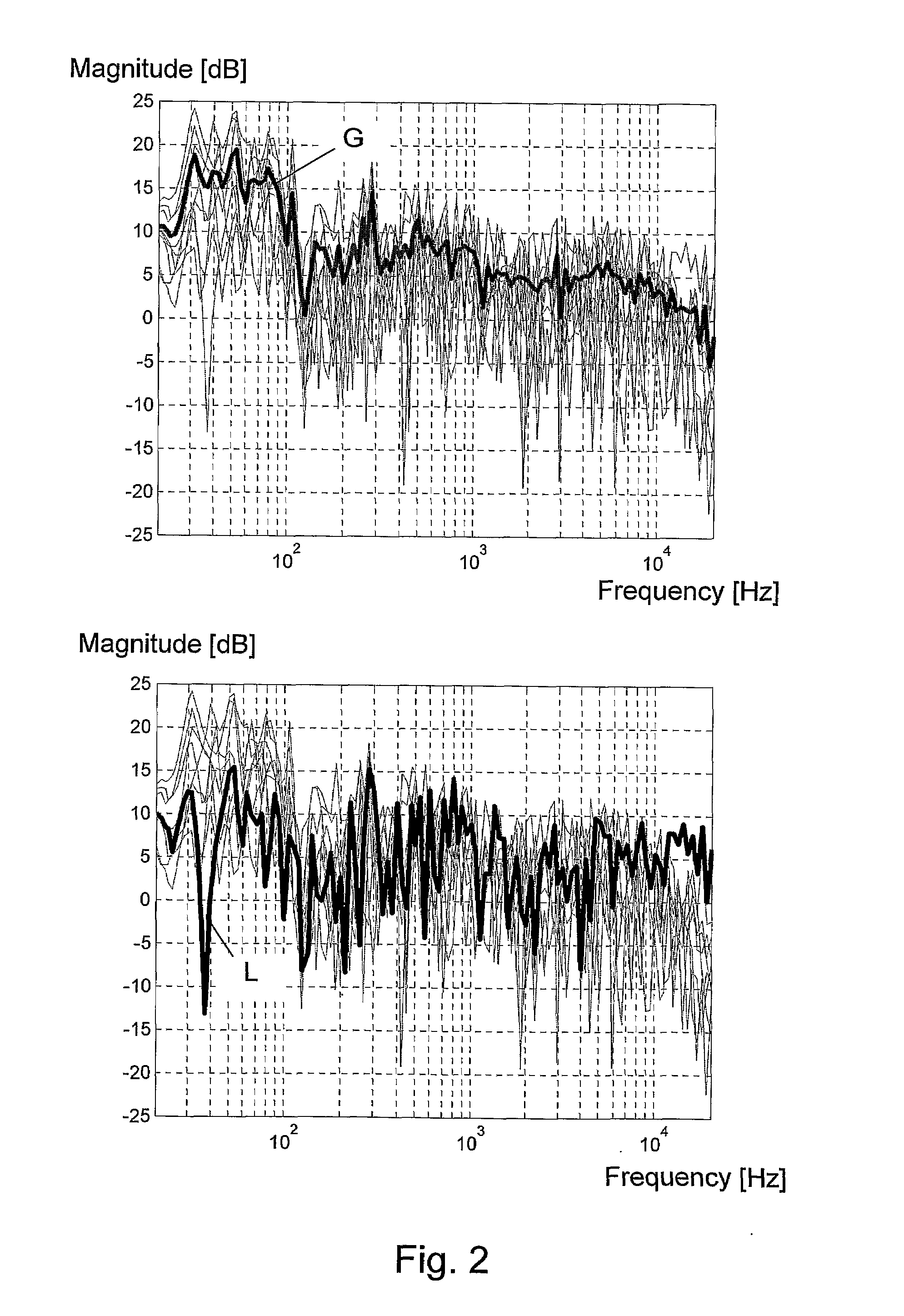
[0016]With the method, it is possible to adapt the equalizing filter to the listening position while still modifying the maximum gain of the filter to follow the general character of the room. Thus, it is possible to avoid designing an equalizing filter with high maximum gains at narrow frequency intervals dictated by local properties in the listening positions. According to the method, such high maximum gains would only be allowed in case they correspond to a general trend in the room. Hereby, the upper gain limit serves to solve the problem of a high gain at specific narrow frequency ranges, e.g. due to a local node in a narrow frequency range in the listening position caused by room mode. The absence of high maximum gains, especially at low frequencies, helps to save power amplifier and loudspeaker dynamic headroom. In addition, it provides a better match to a larger listening area since the specific local acoustic character of the listening position is reduced. Altogether, according to the method it is possible to provide a room adaptation filtering of a loudspeaker which will provide a listener with a listening experience where severe coloration due to room-loudspeaker interaction has been significantly reduced and still without introducing coloration artifacts in locations outside the listening position.
[0032]By these restriction intervals it is possible to further refine the envelope within which the equalizing filter is restricted. This enables, e.g. together with the above-mentioned first and second gains, implementation of an automatic algorithm that will result in a satisfactory equalizing filter without the need for manual assistance from an operator, also in unusual room loudspeaker configurations.
[0035]A filter may be applied to the global transfer function prior to performing step 3). The filter preferably serves to remove a general ‘room gain’ towards lower frequencies, e.g. below 200 Hz. Alternatively or additionally the filter may be arranged to remove an influence of a directivity of the first loudspeaker, this influence being such as a decreasing level towards higher frequencies and thus compensate for the fact that the loudspeaker will in many listening setups be directed with its acoustic high frequency driver pointing towards the listening position, thus causing a higher level at high frequencies here than in the room in general.
[0037]A filter may be applied to at least the listening position transfer function prior to performing step 3), so as to remove a general high-pass effect, such as a high-pass effect introduced by the first loudspeaker. A similar filter may be applied also to the global transfer function. An improved design of the equalizing filter is obtained when the natural cut-off inherent in the loudspeaker is removed prior to performing the filter design.
[0042]It may be preferred to design the first and second equalizing filters to have identical transfer characteristics, thus facilitating the filter design procedure.

Problems solved by technology

This has a number of well-known disadvantages such as uncontrolled high gains at specific low frequencies due to the presence of room modes, unless a number of additional modifications are performed.
Still, these type of equalizing methods may result in a sound reproduction outside the listening position which has a more severe coloration than without the equalizing.
Even very small movements outside the listening position, such as few centimetres, may in some cases be enough to degrade the perceived sound quality significantly.
However, such methods often require a quite large number of measurements, and still provide quite poor results when a listener moves outside a quite narrow listening area.
Thus, in order for such methods to work in general, a large number of manual corrections are needed by a skilled operator.

Method used


Image

  • Method and system for equalizing a loudspeaker in a room
  • Method and system for equalizing a loudspeaker in a room
  • Method and system for equalizing a loudspeaker in a room

Examples


Embodiment Construction

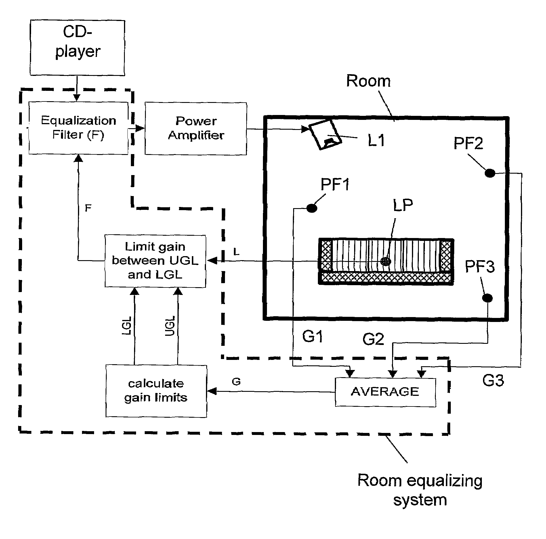
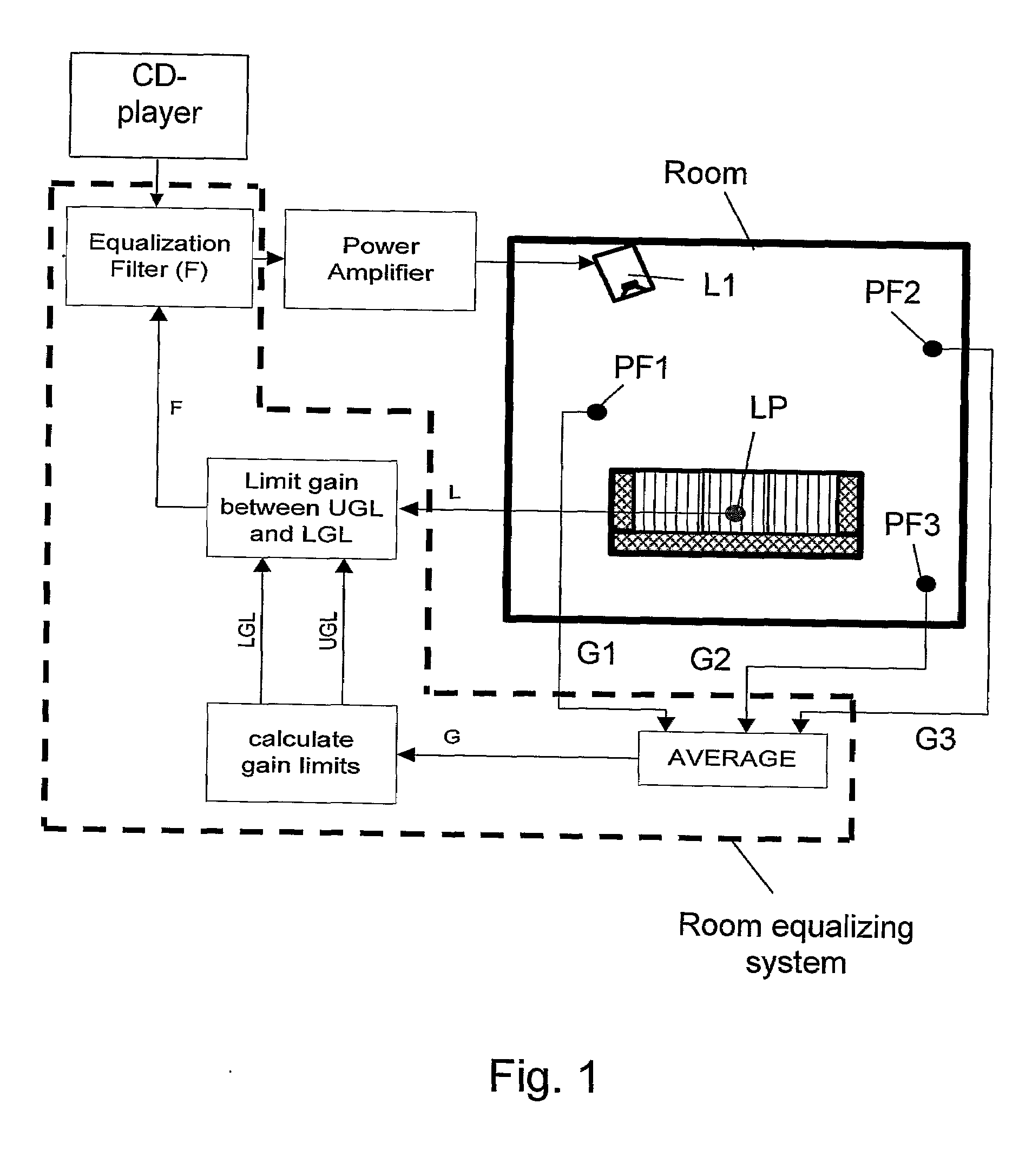
[0068]FIG. 1 serves to illustrate basic elements of a preferred embodiment of the invention. A loudspeaker L1 is positioned in a room, e.g. a living room, with a listening position LP. The loudspeaker L1 may be part of a normal hi-fi stereo setup, such as illustrated by the power amplifier and CD-player connected to the loudspeaker L1. As illustrated, an equalizing filter F, i.e. a pre-filter, according to the invention is inserted in the playback chain between signal source (CD-player) and power amplifier with the main purpose of at least partly compensating sound reproduction in the listening position LP for an influence of the room, or rather an influence from the acoustic interaction between loudspeaker L1 and the room.

[0069]As illustrated, inputs to the room equalizing system are: a) a measured transfer in the listening position transfer function L from electrical input of the loudspeaker L1 to a sound pressure at the listening position, and b) a global transfer function G repr...


PUM


Abstract

A method and a system for equalizing one or more loudspeaker(s), e.g. a hi-fi system, positioned in a room in order to compensate sound reproduction from the loudspeaker for an influence of the room. The method includes measuring a listening position transfer function (L) from electrical input of the loudspeaker (L1) to a sound pressure at a listening position (LP) in the room. A global transfer function (G) representing a spatial average of sound pressure level in the room generated by the loudspeaker (L1) is determined. This global transfer function (G) can either be determined as an average of two or more transfer functions measured in field points scattered across the room or it can be calculated based on an acoustic power output measured from the loudspeaker (L1) together with data regarding sound absorption properties of the room. An upper gain limit (UGL) as a function of frequency is then determined based on an inverse of the global transfer function (G). An equalizing filter (F) is then determined based on an inverse of the listening position transfer function (L), but with its gain being limited to a maximum gain in accordance with the upper gain limit (UGL). Finally, the loudspeaker (L1) is equalized with the equalizing filter (F), the filter (F) being implemented such as a minimum phase approximation by an FIR or an HR filter. Preferably, a lower gain limit (LGL) as a function of frequency is also determined as an inverse of the global transfer function (G), wherein a gain of the equalizing filter (F) is limited to a minimum gain in accordance with the lower gain limit (LGL). By use of the upper and lower gain limits (UGL, LGL) it is possible to implement a system capable of automatically designing the equalizing filter (F) with only simple tasks to perform for an operator of the system.

Description

FIELD OF THE INVENTION[0001]The invention relates to the field of audio and sound reproduction equipment, more specifically the invention provides a method and a system for equalizing a loudspeaker in a room with the purpose of adapting the loudspeaker to the room and thus improve sound reproduction. More specifically, the equalizing is intended to correct a frequency characteristics perceived in a listening position in the room in order to obtain a sound reproduction with a perceived neutral timbre which is more independent of room characteristics, loudspeaker position and listening position in the room.BACKGROUND OF THE INVENTION[0002]Within the field of audio reproduction, such as hi-fi stereo or surround sound systems for home use, it is well-known to apply a pre-equalizing to compensate sound reproduction for the coloration introduced by the listening room, or rather by an interaction between the loudspeaker and the listening room. Different approaches have been made to provide...

Claims


Application Information

Patent Timeline
Patent Type & Authority Applications(United States)
IPC IPC(8): H04R29/00H03G5/00
CPCH04S7/00H04S3/00
Inventor PEDERSEN, JAN ABILDGAARD
Owner SL AUDIO
Learn More