Power module life estimation fatigue function

a technology of fatigue function and power module, applied in the direction of instruments, force/torque/work measurement, instruments, etc., can solve the problems of power module failure, inverter wire crack growth at aluminum wire wedge bond and similar contact points, connections to fatigue and failure,

Active Publication Date: 2009-11-05
ROCKWELL AUTOMATION TECH
View PDF2 Cites 57 Cited by
  • Summary
  • Abstract
  • Description
  • Claims
  • Application Information

AI Technical Summary

Problems solved by technology

After a period of use, however, power modules tend to fail.
A predominant cause of power module failure arises from power cycling, which may cause connections to fatigue and fail.
Moreover, thermal cycling of the type employed by inverters may initiate wire crack growth at aluminum wire wedge bonds and similar contact points, generally occurring at connections to aluminized silicon on the IGBTs.
Strain and fatigue introduced by a mismatch of the coefficient of thermal expansion (CTE) of module materials tends to cause wire crack growth.
New cracks may generally be caused by thermal cycling, leading to fatigue of the bonds of materials of the assembly.
Power modules tend to fail in a predictable manner under constant operating conditions, such as constant maximum junction temperature and median junction temperatures.
Moreover, though strain energy has been applied in models estimating solder joint reliability, such models do not apply directly to bond wire joints and further fail to account for variable operating conditions such as variable junction temperature (Tj) and variable mean junction temperature (Tm).

Method used


Image

  • Power module life estimation fatigue function
  • Power module life estimation fatigue function
  • Power module life estimation fatigue function

Examples


Embodiment Construction

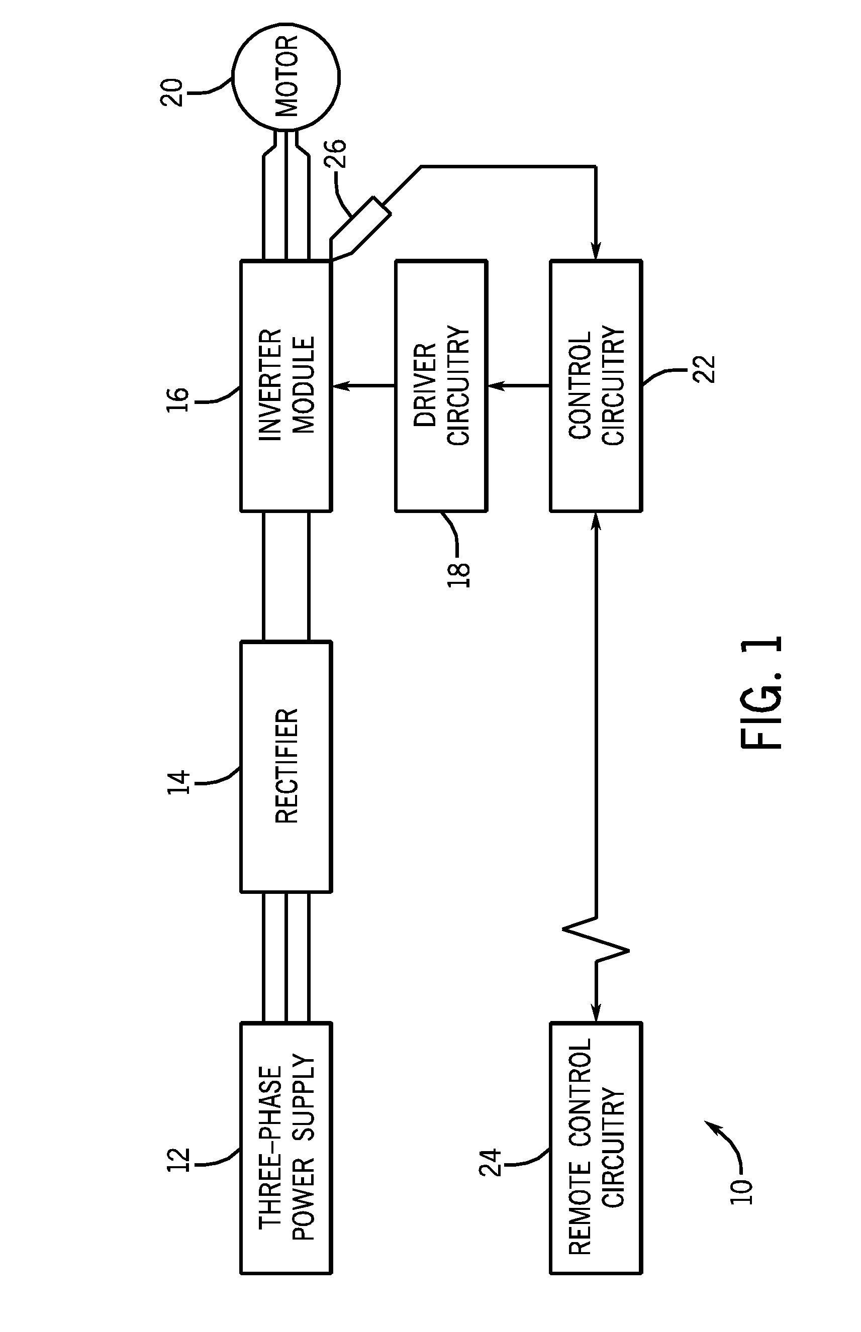
[0027]FIG. 1 illustrates an exemplary motor control system 10 having power module end-of-life prediction circuitry. A three-phase power supply 12 provides a three-phase voltage waveform at a constant frequency to a rectifier 18, and may be derived from a generator or from an external power grid. Rectifier 14 performs full wave rectification of the three phase voltage waveform, outputting a direct current (DC) voltage difference to an inverter module 16. It should be noted that the present invention may be used with three-phase input, common bus input, and regenerative applications.

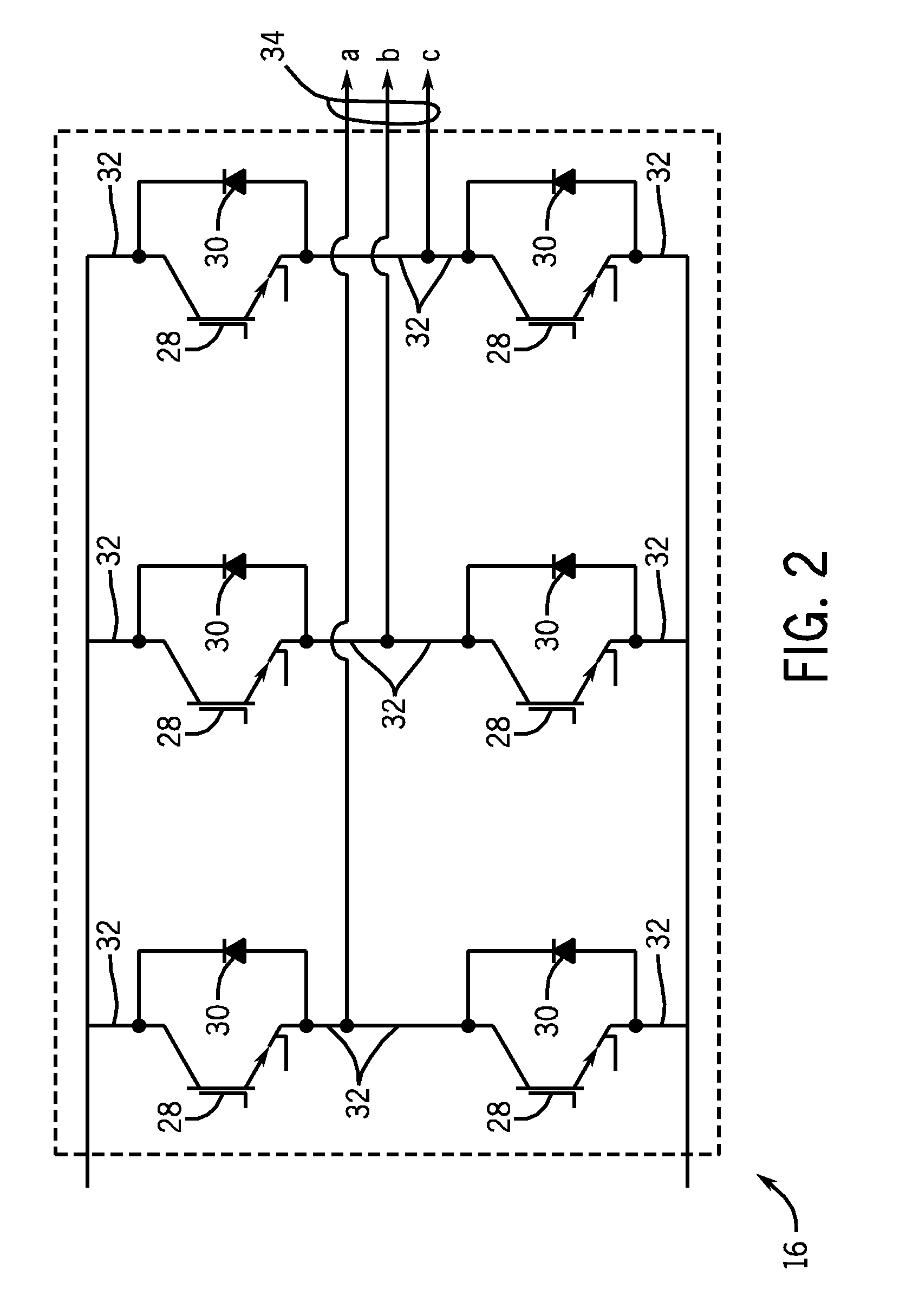
[0028]Inverter module 16 accepts the positive and negative lines of DC voltage from the rectifier circuitry 14 and outputs a discretized three phase waveform at a desired frequency, independent of the frequency of three-phase power supply 12. Driver circuitry18 provides inverter module 16 with appropriate signals, enabling inverter module 16 to output the waveform. The resulting three-phase waveform may th...


PUM


Abstract

A system and method for estimating a condition of a power module is provided. In accordance with an embodiment, a motor controller may be maintained by tracking a total proportion of power module life expended by a power module in a variable frequency motor controller based on a minimum junction temperature or a mean junction temperature and a junction temperature change, and indicating when the power module is estimated to fail.

Description

BACKGROUND[0001]The invention relates generally to the field of electrical power converters and inverters. More particularly, the invention relates to techniques for predicting the life cycle of power modules, such as those used in motor drives.[0002]Power inverters and converters employ power modules to produce a desired power waveform to power various devices, such as motors and other equipment. Power modules generally include power semiconductor switches such as insulated gate bipolar transistors (IGBTs) that are caused to cycle rapidly on and off to produce a desired power waveform. After a period of use, however, power modules tend to fail.[0003]A predominant cause of power module failure arises from power cycling, which may cause connections to fatigue and fail. Moreover, thermal cycling of the type employed by inverters may initiate wire crack growth at aluminum wire wedge bonds and similar contact points, generally occurring at connections to aluminized silicon on the IGBTs....

Claims


Application Information

Patent Timeline
IPC IPC(8): G06F19/00G01K13/00
CPCH02P29/02H02P27/00H01L2224/48472
Inventor WEISS, BRUCE W.WEI, LIXIANG
Owner ROCKWELL AUTOMATION TECH
Why Eureka
Try Eureka