
Thermal conductivity measuring method and apparatus, and gas component ratio measuring apparatus

a technology of thermal conductivity and measuring method, which is applied in the direction of material thermal conductivity, material thermal analysis, instruments, etc., can solve the problems of inability to accurately measure thermal conductivity, difficult to measure its thermal conductivity, and inability to help having a large-scale structure, etc., to achieve the effect of preparing to measure a thermal conductivity

Inactive Publication Date: 2009-11-12
YAMATAKE HONEYWELL CO LTD
View PDF5 Cites 24 Cited by
  • Summary
  • Abstract
  • Description
  • Claims
  • Application Information

AI Technical Summary

Benefits of technology

[0006]It is an object of the present invention to provide thermal conductivity measuring method and apparatus that can readily measure a thermal conductivity of a pure gas or a mixed gas. Further, it is an object of the present invention to provide a gas component ratio measuring apparatus that can obtain composition ratios of a mixed gas whose type is known, e.g., a natural gas to evaluate a calorific value by using the thermal conductivity measuring method and apparatus.

Problems solved by technology

However, when adopting this technique to measure a thermal conductivity of the ambient gas, this technique cannot help having a large-scale structure because, e.g., a constant-temperature bath that maintains the ambient temperature at a fixed temperature is required.
However, since a thermal conductivity of a gas generally has intrinsic temperature change characteristics according to a type of this gas, there is a fundamental problem that the thermal conductivity cannot be accurately measured by simply measuring a calorific value of a heater.
In particular, when a mixed gas in which a plurality of types of gases are mixed like a natural gas is an ambient gas, measuring its thermal conductivity is very difficult.
However, such a technique has a problem that analysis of the composition ratios of the mixed gas by using the column requires a long time and an entire structure of an analysis apparatus is completed and expensive, for example.

Method used


Image

  • Thermal conductivity measuring method and apparatus, and gas component ratio measuring apparatus
  • Thermal conductivity measuring method and apparatus, and gas component ratio measuring apparatus
  • Thermal conductivity measuring method and apparatus, and gas component ratio measuring apparatus

Examples


Embodiment Construction

[0029]A thermal conductivity measuring method, a thermal conductivity measuring apparatus, and a gas component ratio measuring apparatus according to the present invention will now be explained hereinafter with reference to the accompanying drawings.

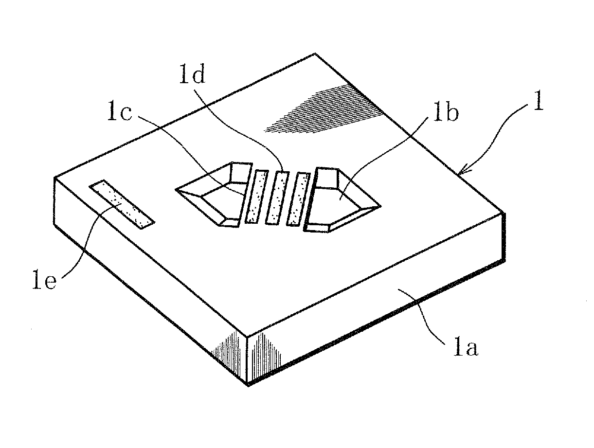
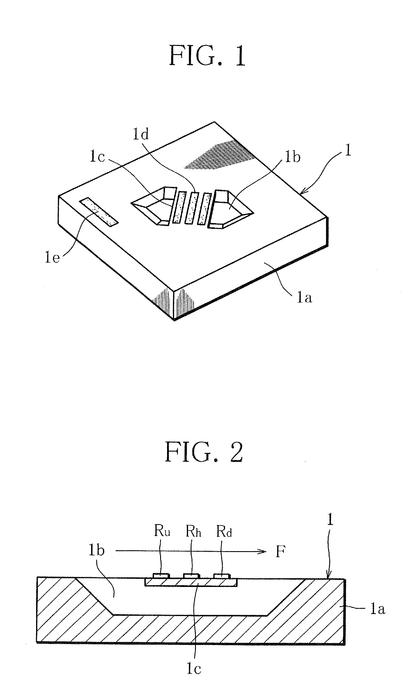
[0030]According to the present invention, for example, a microheater 1 whose outline structure is shown in FIG. 1 is used to basically measure a thermal conductivity of an ambient gas (a pure gas or a mixed gas) from a calorific value of the microheater 1. In the microheater 1, a concave cavity 1b is formed on a surface of a silicon chip 1a having, e.g., a diameter of 0.5 mm and a dimension of approximately 1.5 mm square, a bridge is thrown over this cavity 1b to form a thin-film-like diaphragm 1c, and a small heat generating resistive element (a heater) 1d formed of, e.g., platinum is provided on this diaphragm 1c. Further, a temperature sensor 1e that measures an ambient temperature is generally provided at a peripheral portion of the ...


PUM


Abstract

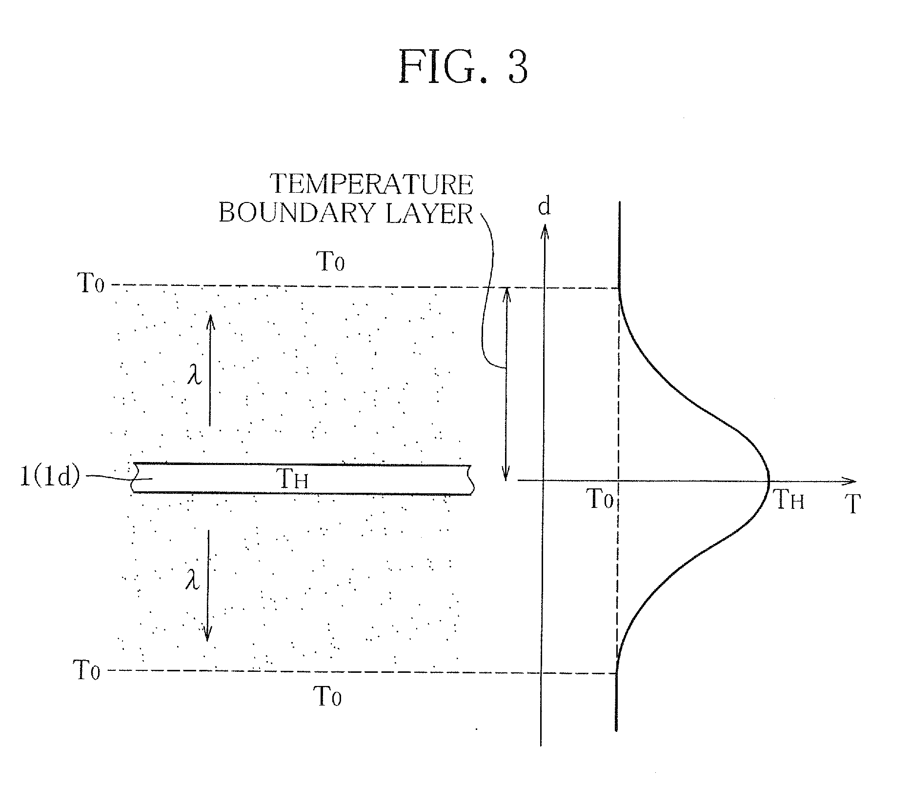
A heat radiation coefficient C [=Ph / (Th−To)] from a microheater is calculated in accordance with a power Ph applied to the microheater which is supported in air and provided in an ambient gas, a heater temperature Th, and an ambient temperature To at this moment. Further, a thermal conductivity λ(T) of the ambient gas is obtained from the calculated heat radiation coefficient C based on a proportional relation [C=K·λ(T)] between a thermal conductivity λ(T) of the ambient gas and the heat radiation coefficient C at a measurement temperature T [=(Th−To) / 2].

Description

TECHNICAL FIELD[0001]The present invention relates to thermal conductivity measuring method and apparatus that can readily measure a thermal conductivity of a gas whose type is known but whose component ratios (composition ratios) are unknown, e.g., a natural gas, and a gas component ratio measuring apparatus using the thermal conductivity measuring apparatus.BACKGROUND ART[0002]As a technique of measuring a thermal conductivity of a gas, driving a heater at a fixed temperature in a state where an ambient gas surrounding the heater is maintained at the fixed temperature and measuring a calorific value of the heater is known. This technique utilizes the fact that a calorific value of the heater is in proportion to a thermal conductivity of the ambient gas. However, when adopting this technique to measure a thermal conductivity of the ambient gas, this technique cannot help having a large-scale structure because, e.g., a constant-temperature bath that maintains the ambient temperature...

Claims


Application Information

Patent Timeline
IPC IPC(8): G01N25/18
CPCG01N33/225G01N27/18G01N25/18
Inventor OOISHI, YASUHARUAOSHIMA, SHIGERUSHINGYOUJI, NOBUYOSHIHAYASHI, YASUEMORIO, SHUJI
Owner YAMATAKE HONEYWELL CO LTD
Learn More