Cooling system

a cooling system and cooling system technology, applied in the direction of engine cooling apparatus, machines/engines, mechanical equipment, etc., can solve the problems of increasing the stress level of cooling system components made of plastic materials or rubber, insufficient air cooling to cool the engine, and components that get significantly more expensive, so as to increase the coolant pressure

Inactive Publication Date: 2009-11-12
VOLVO LASTVAGNAR AB
View PDF4 Cites 25 Cited by
  • Summary
  • Abstract
  • Description
  • Claims
  • Application Information

AI Technical Summary

Benefits of technology

[0009]One efficient, known, way of reducing the problems with cavitation and boiling after engine shut-off is to increase the coolant pressure. This is however rather expensive, since the expansion tank must be a vessel standing high pressures, i.e. a vessel having thick walls.
[0010]U.S. Pat. No. 4,346,757 describes an automotive vehicle cooling system having a radiator connected to the engine coolant jacket for circulation of coolant, a pump delivering coolant from the radiator to the engine, a non-pressurized reservoir bottle, or expansion vessel, communicating with a radiator and having a make-up line communicating with a Venturi in a recirculating line around the pump directing coolant from the pump outlet to the pump inlet. The Venturi allows make-up coolant to be added from the reservoir bottle at atmospheric pressure so that the bottle can be of a relatively light-weight gauge material.

Problems solved by technology

On modern, high performance engines, air-cooling is not sufficient to cool the engine; instead, a cooling system with a coolant is arranged.
There are however some problems to be solved relating to water cooling: Firstly, there is a trend towards higher coolant temperatures; a high coolant temperature gives a higher maximum cooling rate (due to a larger temperature difference between the coolant and the ambient air) and also less heat transfer from the engine's combustion chambers to the coolant, which is beneficial for engine efficiency.
The higher temperatures lead to higher stress levels on cooling system components made of plastic materials or rubber.
Especially the expansion chamber (a component well known by persons skilled in the art) is a component that gets significantly more expensive if it should stand elevated coolant temperatures.
Secondly, water-cooling systems have problems with cavitation; cavitation means that a liquid is forced to boil by decompression, which gives gas bubbles in the liquid; these gas bubbles have, however, a very short life; as soon as the pressure in the liquid returns to normal levels, the bubbles will implode to liquid.
Cavitation is detrimental to cooling system components due to the “micro-shocks” resulting from the bubble implosions, and is rather common in cooling systems.
Thirdly, water-cooling systems have problems with boiling after engine shut-off; after the engine has been shut off, the coolant will stop circulating in the cooling system.
The volume increase emanating from boiling might force coolant out from the cooling system, which leads to increased coolant consumption.
Fourthly, air entrainment might (or rather, will) pose a problem if the coolant is not deaerated continuously.
In prior art system, the deaeration of the coolant will take place in the expansion chamber, but as will be evident in the following, this is a solution that will not be very efficient in the future.
This is however rather expensive, since the expansion tank must be a vessel standing high pressures, i.e. a vessel having thick walls.
Consequently, the design according to U.S. Pat. No. 4,346,757 does not in any way address the problem of boiling after engine shut-off.
One problem with subjecting an expansion vessel for compressed air, is that this type of vessel will “breathe” frequently and coolant can escape from the vessel each time the inlet valve is opened.

Method used


Image

  • Cooling system
  • Cooling system
  • Cooling system

Examples


Embodiment Construction

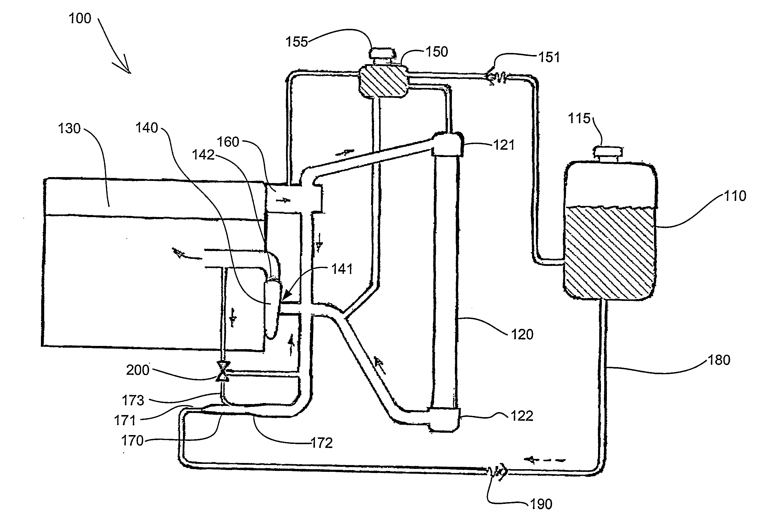
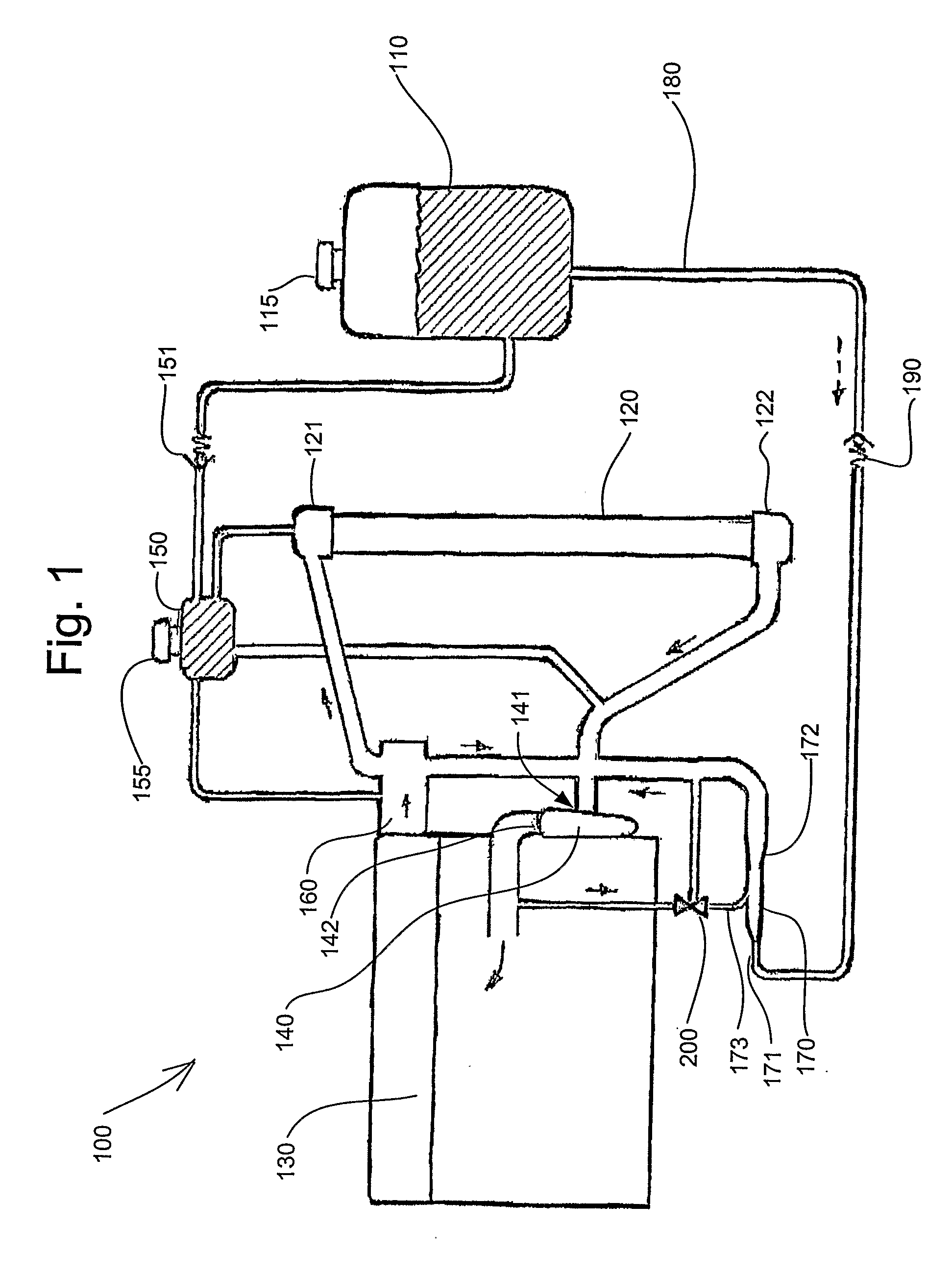
[0024]In FIG. 1, a cooling system 100 according to the present invention is shown schematically. The cooling system 100 comprises an expansion tank 110, a radiator 120, a cooling system of an engine 130, a coolant pump 140, a deaeration tank 150, a thermostat housing 160 and an ejector pump 170 as well as piping, hosing or ducting connecting these components in a way that will be described below.

[0025]The expansion tank 110 is provided with a coolant outlet hose 180 connecting the expansion tank 110 to an ejector pump inlet 171 of the ejector pump 170. A one-way valve 190 in the hose 180 allows a flow of coolant from the expansion tank 110 to the ejector pump 170, but stops coolant from flowing in the opposite direction.

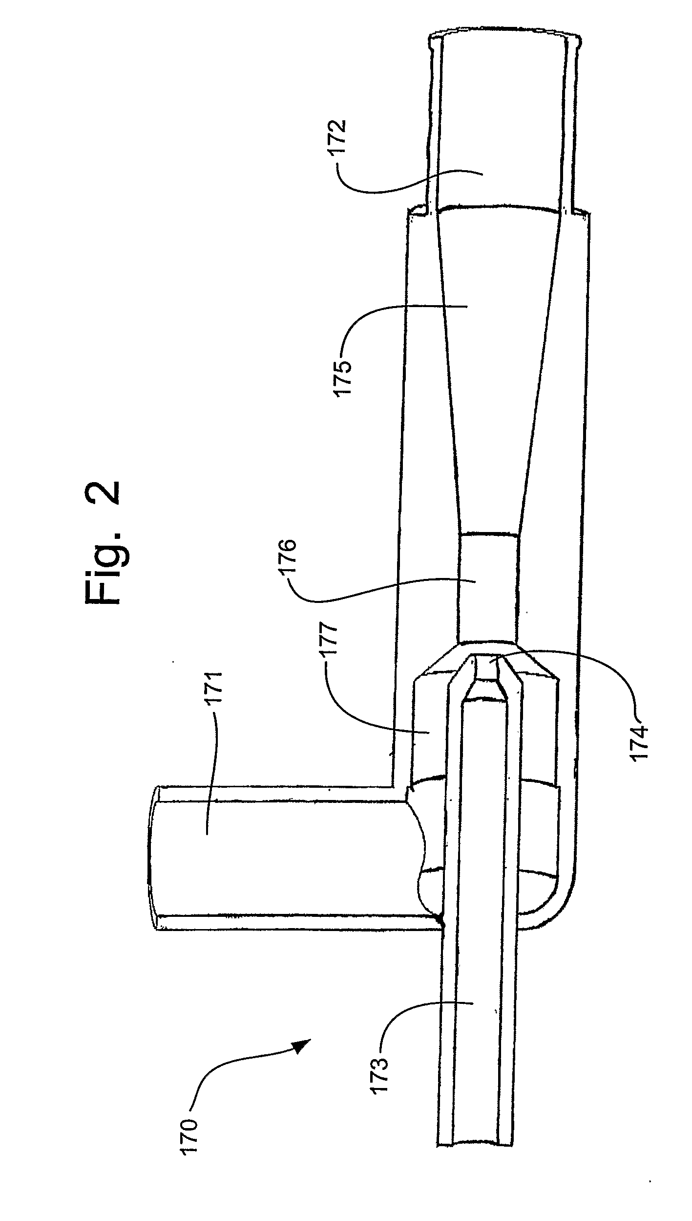
[0026]An ejector pump outlet 172 of the ejector pump 170 is connected to a coolant inlet 141 of the coolant pump 140. A coolant outlet 142 of the coolant pump is connected to the internal cooling system of the engine 130. Moreover, a power connection 173 of the eject...


PUM


Abstract

A cooling system for an engine is divided into an inner circuit and an outer circuit, said inner circuit including a radiator, a cooling pump, a thermostat housing, an ejector pump, cooling channels arranged inside the engine and ducting connecting said components. The ejector pump is arranged to draw coolant from the outer system and deliver it to the inner system. The outer system includes an expansion tank, ducting interconnecting the expansion tank and the ejector pump and ducting interconnecting the inner circuit and the expansion tank. A one-way valve is placed in the ducting interconnecting the expansion tank and the inner circuit.

Description

BACKGROUND AND SUMMARY[0001]The present invention relates to a cooling system for an engine, said cooling system being divided into an inner circuit and an outer circuit. The inner circuit comprises a radiator, a cooling pump, a thermostat housing, an ejector pump and cooling channels arranged inside the engine. The ejector pump is arranged to draw coolant from the outer system, which comprises an expansion tank, ducting interconnecting the expansion tank and the ejector pump and ducting interconnecting the inner circuit and the expansion tank and deliver it to the inner system.[0002]Moreover, the present invention relates to an ejector pump for pressurizing a cooling system of a combustion engine.[0003]As is well known by persons skilled in the art, the main purpose of a cooling system of an engine is to transfer heat generated in the engine to a radiator, where the heat could be vented to the ambient air. In its simplest form, a cooling system could comprise area-increasing metal ...

Claims


Application Information

Patent Timeline
Patent Type & Authority Applications(United States)
IPC IPC(8): F01P7/14
CPCF01P2005/105F01P11/028
Inventor THEORELL, GUNNAR
Owner VOLVO LASTVAGNAR AB
Why Eureka
Try Eureka