Diluting fuel-in-oil separating apparatus of internal combustion engine

a technology of internal combustion engine and separation apparatus, which is applied in the direction of mechanical equipment, lubricant mounting/connection, machines/engines, etc., can solve the problems of significant heat energy loss

Inactive Publication Date: 2009-11-12
TOYOTA BOSHOKU KK
View PDF6 Cites 34 Cited by
  • Summary
  • Abstract
  • Description
  • Claims
  • Application Information

AI Technical Summary

Benefits of technology

[0010]The present invention is described hereinafter.
[0011]1. A diluting fuel-in-oil separating apparatus of an internal combustion engine includes an oil container configured to contain lubricating oil of the internal combustion engine and have a first compartment and a second compartment divided from the first compartment, such that the lubricating oil is introduced from the first compartment into the second compartment; and a fuel eliminator configured to eliminate fuel from the lubricating oil in the first compartment. The second compartment is provided with an oil passage having an oil pump configured to supply the lubricating oil from the second compartment to lubricated parts of the internal combustion engine.
[0012]2. According to the diluting fuel-in-oil separating apparatus of the internal combustion engine described in above 1, the fuel eliminator includes a heater configured to heat the lubricating oil of the internal combustion engine; the first compartment is configured to contain the lubricating oil heated by the heater; and the second compartment is divided from the first compartment, such that the

Problems solved by technology

However, heat energy losses are significant in the technology disclosed in Related Art 1, since the heater heats a relatively large amount of the lubricating oil flowing in an oil passage that connects the oil pan to lubricated

Method used


Image

  • Diluting fuel-in-oil separating apparatus of internal combustion engine
  • Diluting fuel-in-oil separating apparatus of internal combustion engine
  • Diluting fuel-in-oil separating apparatus of internal combustion engine

Examples


embodiment

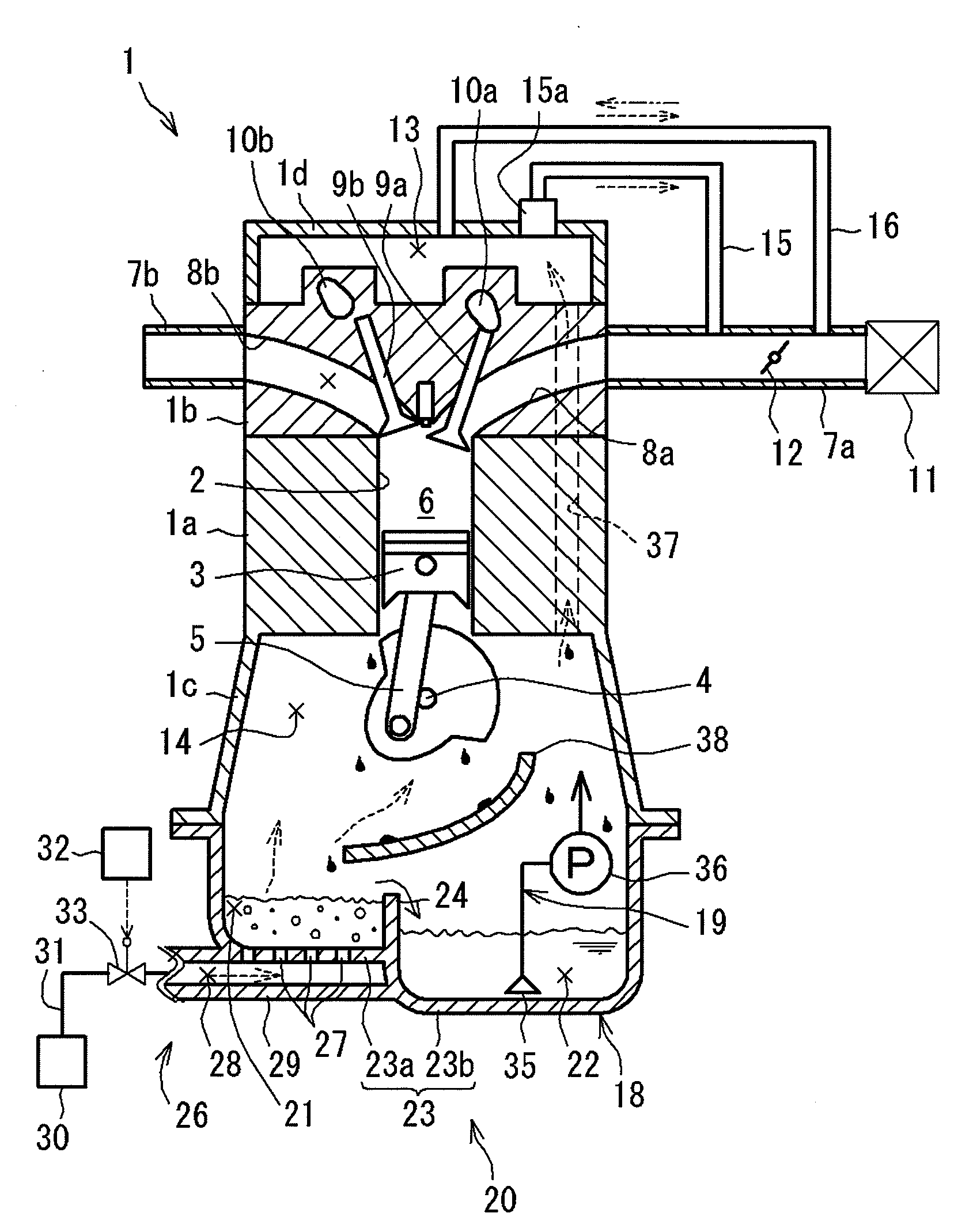
[0063]Hereinafter, first to third embodiments of the present invention will be described in detail with reference to the drawings. In the first to third embodiment, a cylinder injection type internal combustion engine is described as an example of an “internal combustion engine”according to the present invention, the cylinder injection type internal combustion engine performing a secondary injection before and after a primary injection.

[0064](1) Configuration of Engine

As shown in FIG. 1, an engine 1 according to the first embodiment includes a cylinder block 1a provided with a cylinder 2 and a cylinder head 1b fixed to an upper portion of the cylinder block 1a. A piston 3 is reciprocably supported inside the cylinder 2 of the cylinder block 1a. A crankcase 1c rotatably supporting a crankshaft 4 is fixed to a lower portion of the cylinder block 1a. The crankshaft 4 is connected to the piston 3 via a connecting rod 5. A combustion chamber 6 is provided above the piston 3, the combusti...


PUM


Abstract

The diluting fuel-in-oil separating apparatus includes an oil container (an oil pan) and a fuel eliminator (a heater, a bubble generator). The oil container contains lubricating oil of the internal combustion engine, and has a first compartment and a second compartment divided from the first compartment, such that the lubricating oil is introduced from the first compartment into the second compartment. The fuel eliminator eliminates fuel from the lubricating oil in the first compartment. The second compartment is provided with an oil passage having an oil pump supplying the lubricating oil from the second compartment to lubricated parts of the internal combustion engine.

Description

CROSS-REFERENCE TO RELATED APPLICATIONS[0001]The present application claims priority under 35 U.S.C. §119 of Japanese Patent Application Nos. 2008-124031 and 2008-124030, filed on May 9, 2008, the disclosure of which is expressly incorporated by reference herein in its entirety.BACKGROUND OF THE INVENTION[0002]1. Field of the Invention[0003]The present invention relates to diluting fuel-in-oil separating apparatuses of internal combustion engines and, more particularly, the present invention relates to a diluting fuel-in-oil separating apparatus of an internal combustion engine that can efficiently separate the fuel from the lubricating oil of the internal combustion engine while suppressing degradation of the oil.[0004]2. Description of Related Art[0005]Known conventional diluting fuel-in-oil separating apparatuses of internal combustion engines heat lubricating oil and separate the fuel from the lubricating oil by vaporization in order to suppress dilution of the lubricating oil w...

Claims


Application Information

Patent Timeline
IPC IPC(8): F01M5/00F01N5/02F01M11/03
CPCF01M11/0004F01M2001/165F01M2011/0037F01M2011/0033F01M2011/0025
Inventor SAITO, YASUHIRO
Owner TOYOTA BOSHOKU KK
Why Eureka
Try Eureka