Apparatus and die for welding plastic and a method of use thereof

Active Publication Date: 2009-11-12
SOLMAX INT
View PDF6 Cites 0 Cited by
  • Summary
  • Abstract
  • Description
  • Claims
  • Application Information

AI Technical Summary

Benefits of technology

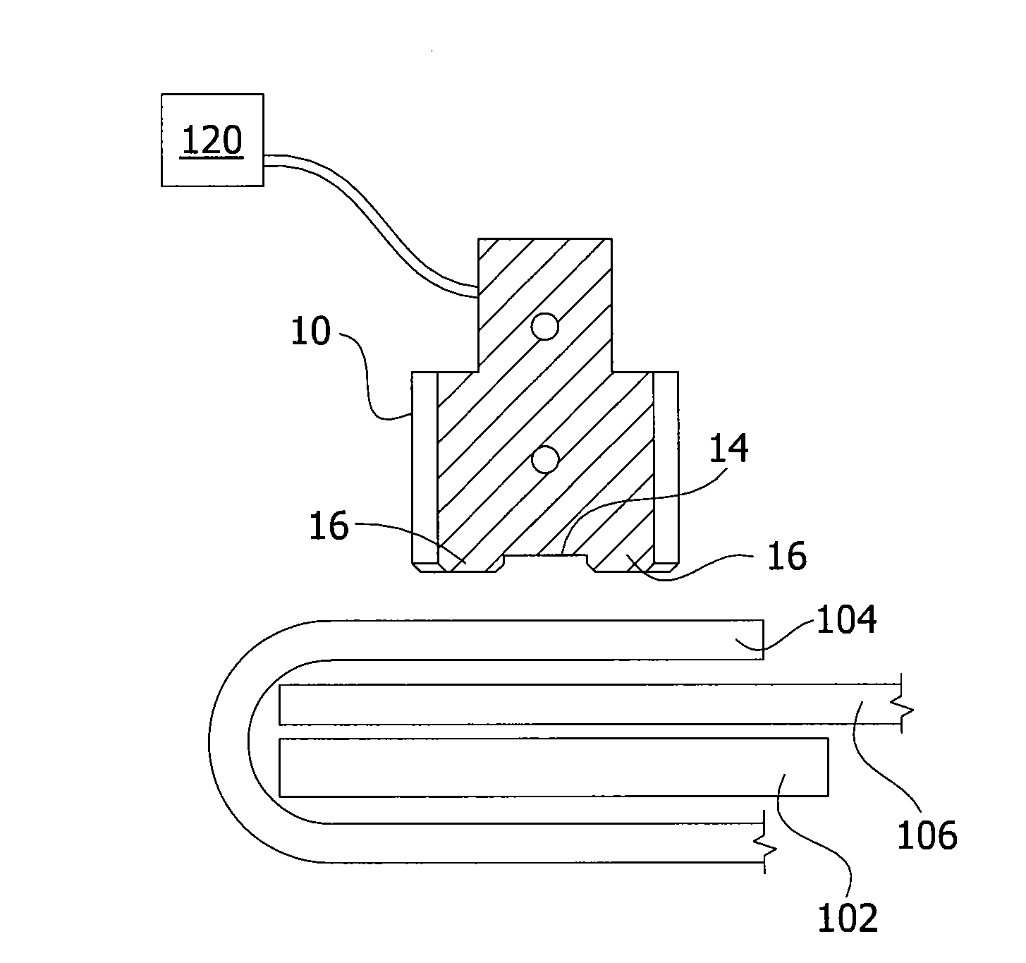
[0023]wherein the depth of the die channel prevents the formation of an electromagnetic field that is st

Problems solved by technology

This type of welding requires each joint be formed in a single pass and therefore the size of any resultant plastic panel is limited by the size of the area in which the welding is taking place.
Furthermore, it is know that both Hot Wedge and Hot Air welding are not well suited to welding thinner materials, such as those having a thickness of 30 thousandths of an inch or less, wherein, for example, the heat source may be positioned very close

Method used


Image

  • Apparatus and die for welding plastic and a method of use thereof
  • Apparatus and die for welding plastic and a method of use thereof
  • Apparatus and die for welding plastic and a method of use thereof

Examples


Example

[0043]In the following description, the same numerical references refer to similar elements. The embodiment shown in the figures is preferred, for exemplification purposes only.

[0044]Although the preferred embodiment of the present invention as illustrated in the accompanying drawings comprises various components, etc., and although the preferred embodiment of the present invention as shown consists of certain geometrical configurations as explained and illustrated herein, not all of these components and geometries are essential to the invention and thus should not be taken in their restrictive sense, i.e. these components and geometries should not be taken as to limit the scope of the present invention. It is to be understood, as also apparent to a person skilled in the art, that other suitable components and cooperations therebetween, as well as other suitable geometrical configurations may be used according to the present invention, without departing from the scope of the inventi...


PUM

PropertyMeasurementUnit
Frequencyaaaaaaaaaa

Abstract

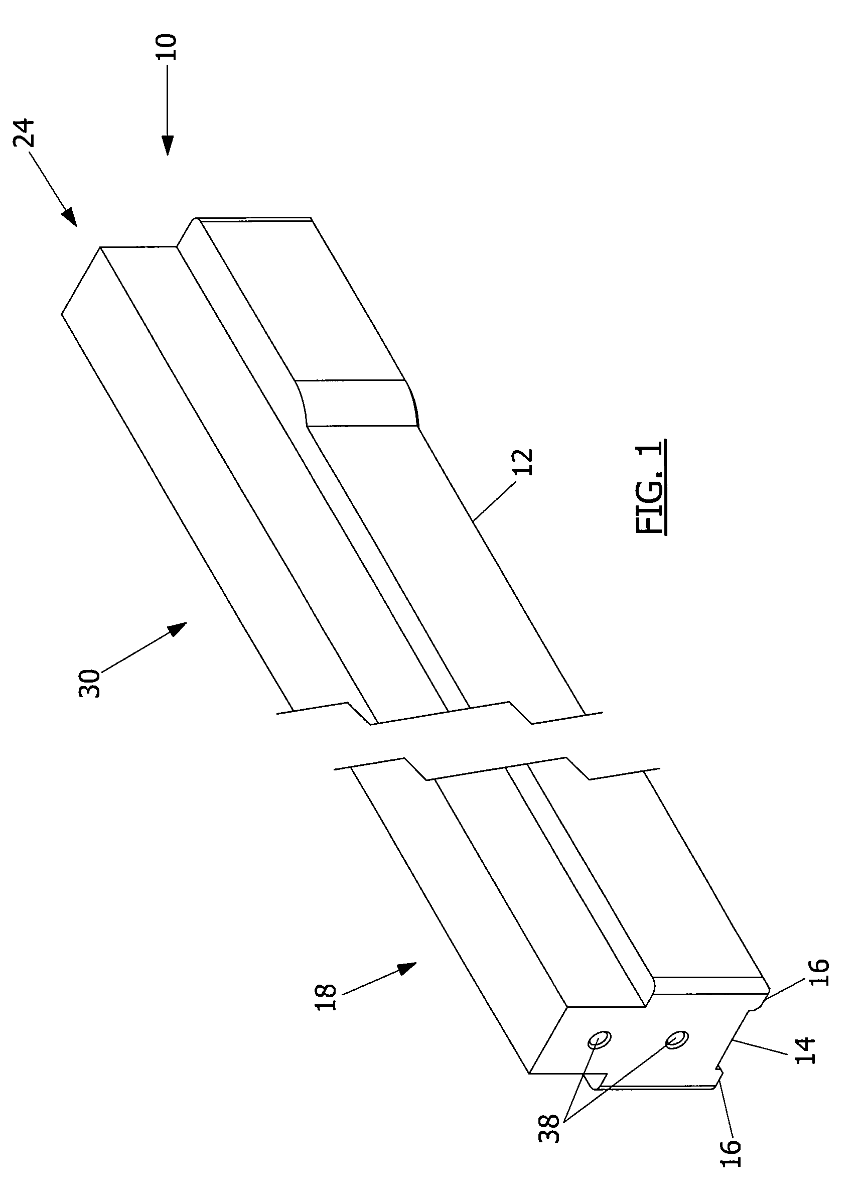
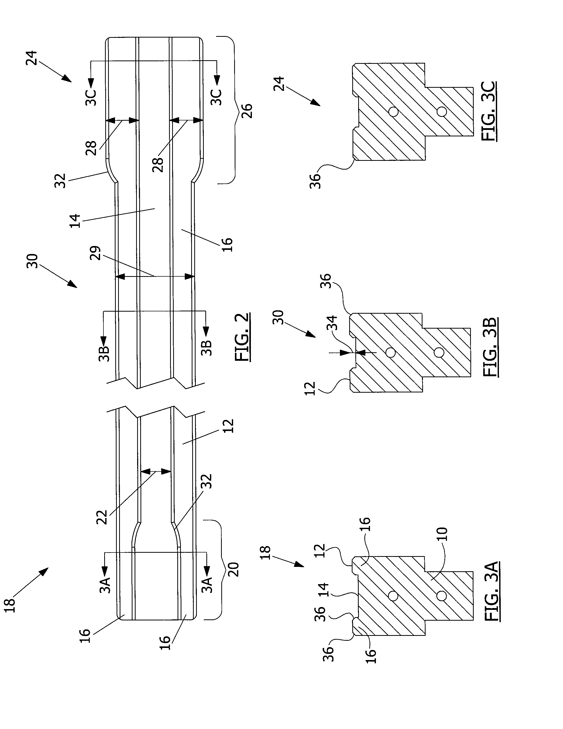
An apparatus for welding a first plastic sheet to a second plastic sheet is provided. The apparatus includes an elongate die including a channel extending longitudinally along the die's welding face. In combination with a plate and a high frequency alternating current generator, the die and the plate are operable to compress the first and second plastic sheets in an overlapping arrangement and generate a high frequency alternating electromagnetic field between the die and the plate and weld the first and second plastic sheets to one another. The depth of the die channel prevents the formation of an electromagnetic field that is strong enough to weld the first and second plastic sheets in an area between the die channel and the plate. A die for use in such an apparatus and a method of use thereof are further provided.

Description

FIELD OF THE INVENTION[0001]The present invention relates to an apparatus for joining plastic sheets and the like. More particularly, and in its preferred intended use, the present invention relates to an apparatus for joining two plastic sheets by radio frequency welding, a die for use in such an apparatus and a method of use thereof.BACKGROUND OF THE INVENTION[0002]Apparatuses for joining plastic materials, and their methods of use, are well known in the art. Typically, two or more plastic pieces are heated so that the long chain molecules of the plastic material loosen as the material transitions to a liquid phase. When subsequently cooled, the long chain molecules intertwine and solidify, thereby fusing the two sheets together.[0003]Various apparatuses and methods are known for welding plastics. For example, Hot Wedge welding applies heated elements directly to the plastic material, while Hot Air welding, as the name suggests, applies heated air to the material. It is also known...

Claims


Application Information

Patent Timeline
IPC IPC(8): B29C65/02
CPCB29C66/3472B29C66/91655B29K2905/02B29K2077/00B29K2075/00B29K2067/00B29K2055/02B29K2027/06B29K2023/083B29K2023/06B29C65/04B29C65/82B29C65/8246B29C66/0044B29C66/1122B29C66/232B29C66/324B29C66/3452B29C66/81427B29C66/43B29C66/80B29C66/8122B29C66/9161B29C66/954B29C65/00B29K2827/18B29C66/8322B29C66/81811B29C66/71B29K2067/003
Inventor GERMAIN, JEAN-PAULSHANNON, STEVE
Owner SOLMAX INT
Why Eureka
Try Eureka