Tunable Thermal Link

a phonon transport and thermal link technology, applied in the field of nanomaterials, can solve the problems of lack of variability and tunability of phonon transport in materials, no devices have been shown to exhibit tunable thermal conductance, etc., to achieve large thermal conductivity effect, increase or decrease longitudinal separation, and increase separation

Active Publication Date: 2009-11-12
RGT UNIV OF CALIFORNIA
View PDF12 Cites 18 Cited by
  • Summary
  • Abstract
  • Description
  • Claims
  • Application Information

AI Technical Summary

Benefits of technology

[0017]As described below, the present invention involves a finding that that small movements which cause increased or decreased longitudinal (axial) separation caused by telescoping outer layers of an MWNT (“multiwalled nanotube”) or related structure have a large effect on thermal conductivity (“K”), in view of the very high K values which carbon nanotubes (essentially rolled up graphitic sheet) have been shown to possess. That is, the MWNT structures described below do not behave as conventional thermal conductors. Sliding concentric (conventional) metallic cylinders, even with a large thermal conductance, would not show this effect. Nonlinearity and short phononic localization length are two important properties of nanotubes. If nanotubes were traditional thermal conductors, the reduction of thermal conductance would scale linearly with separation length. The range of tunability is a function of the phononic localization length. The phononic localization length can depend on the size of the gap or the number of nanotube walls being compromised.
[0018]The fact that nanotubes are not traditional thermal conductors can be seen from the nonlinear response curve for increasing separation. This is shown in FIG. 4 and confirme...

Problems solved by technology

In addition, unlike typical field-effect transistors, which can change on-off resistances by more than 106, no devices have been shown to exhibit tunable thermal conducta...

Method used


Image

  • Tunable Thermal Link
  • Tunable Thermal Link
  • Tunable Thermal Link

Examples


example 1

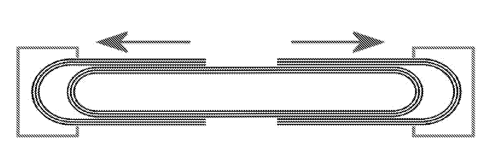
MWCNTs as a Thermal Nano-Mechanical Rheostat

[0070]MWCNTs with diameters ranging from 10 nm to 33 nm were prepared using conventional arc methods.

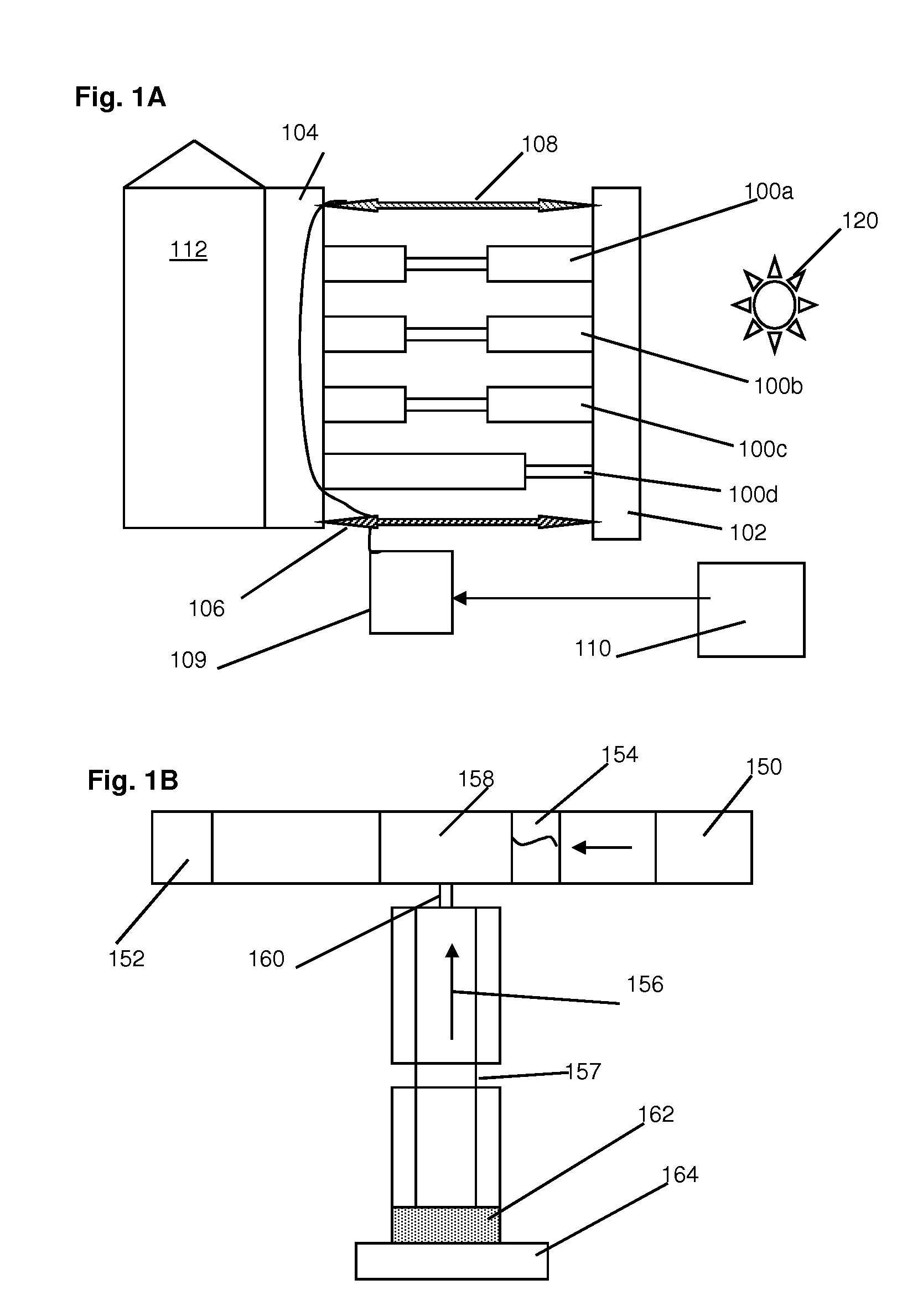
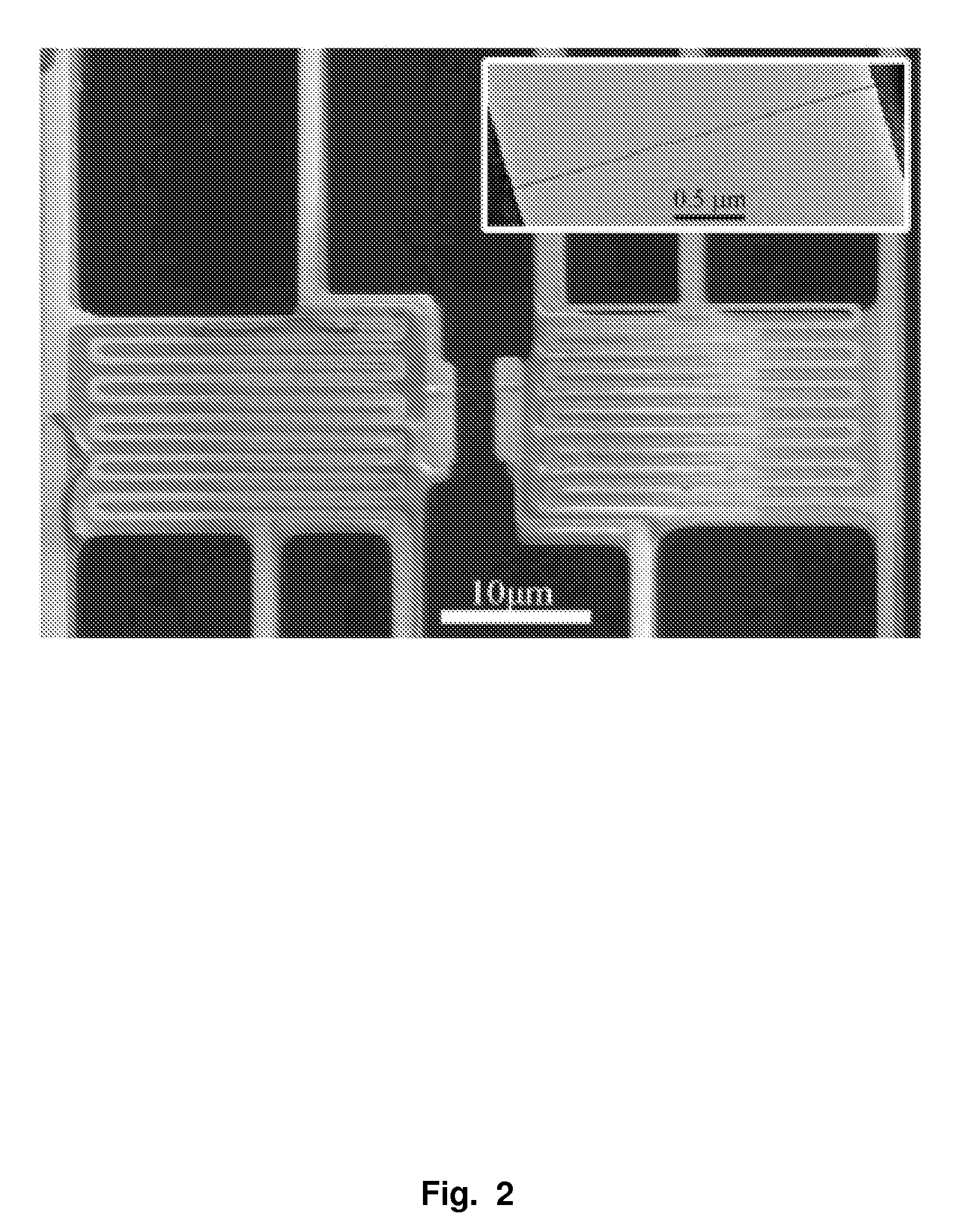
[0071]Individual tubes were placed on a custom designed microscale thermal conductivity test fixture using a piezo-driven manipulator operated inside an SEM. Details of the test fixture fabrication process have been published elsewhere (see Shi et al, “Measuring Thermal and Thermoelectric Properties of One-Dimensional Nanostructures Using a Microfabricated Device,”J. Heat Transfer, 125, 881 (2003)). In brief, the fixture incorporates independently suspended heat source and heat sink pads, with integrated Pt film resistors serving symmetrically either as heaters or sensors (i.e., thermometers). The fixture was made adaptable to TEM imaging by wet etching a window through the exposed Si below the sample mount region. Nanotubes were bonded to the source / sink pads using (trimethyl) methylcyclopentadienyl platinum ((CH3)3(CH3C5H4)Pt) for mechani...


PUM

PropertyMeasurementUnit
Fractionaaaaaaaaaa
Nanoscale particle sizeaaaaaaaaaa
Frequencyaaaaaaaaaa

Abstract

Disclosed is a device whereby the thermal conductance of a multiwalled nanostructure such as a multiwalled carbon nanotube (MWCNT) can be controllably and reversibly tuned by sliding one or more outer shells with respect to the inner core. As one example, the thermal conductance of an MWCNT dropped to 15% of the original value after extending the length of the MWCNT by 190 nm. The thermal conductivity returned when the tube was contracted. The device may comprise numbers of multiwalled nanotubes or other graphitic layers connected to a heat source and a heat drain and various means for tuning the overall thermal conductance for applications in structure heat management, heat flow in nanoscale or microscale devices and thermal logic devices.

Description

CROSS-REFERENCE TO RELATED APPLICATIONS[0001]This application claims priority from U.S. Provisional Patent Application No. 61 / 051,187 filed on May 7, 2008, which is hereby incorporated by reference in its entirety.STATEMENT OF GOVERNMENTAL SUPPORT[0002]This invention was made with U.S. Government support under Contract Number DE-AC02-05CH11231 between the U.S. Department of Energy and The Regents of the University of California for the management and operation of the Lawrence Berkeley National Laboratory. The U.S. Government has certain rights in this invention.REFERENCE TO SEQUENCE LISTING, COMPUTER PROGRAM, OR Compact Disk[0003]NoneBACKGROUND OF THE INVENTION[0004]1. Field of the Invention[0005]The present invention relates to the field of nanomaterials such as carbon nanotubes and further to the field of thermal switches.[0006]2. Related Art[0007]Presented below is background information on certain aspects of the present invention as they may relate to technical features referred...

Claims


Application Information

Patent Timeline
IPC IPC(8): F28F21/02F28F27/00B23P15/26
CPCY10T29/4935F28F21/02B82Y10/00F28F27/00F28F2013/008
Inventor CHANG, CHIH-WEIMAJUMDAR, ARUNAVAZETTL, ALEXANDER K.
Owner RGT UNIV OF CALIFORNIA
Why Eureka
Try Eureka