Plasma cutter with disconnectable torch and work assemblies

a technology of cutting torch and work assembly, which is applied in the field of plasma cutting system, can solve the problems of difficult coiling, awkward and inefficient storage shape, and prohibit cable storag

Active Publication Date: 2009-11-12
ILLINOIS TOOL WORKS INC
View PDF9 Cites 24 Cited by
  • Summary
  • Abstract
  • Description
  • Claims
  • Application Information

AI Technical Summary

Problems solved by technology

However, when not in use, the user must manage lengthy cables during transport or storage.
Since one end of each cable of a traditional plasma cutting system is permanently attached to the power supply unit, coiling is difficult because only one end of each cable can rotate freely.
Another difficulty associated with permanently connected cables is that the permanent attachment prohibits the storage of the cables in alternative locations.
Further, the fixed ends of the cables generally extend outward, which leads to an awkward and inefficient storage shape.

Method used


Image

  • Plasma cutter with disconnectable torch and work assemblies
  • Plasma cutter with disconnectable torch and work assemblies
  • Plasma cutter with disconnectable torch and work assemblies

Examples


Embodiment Construction

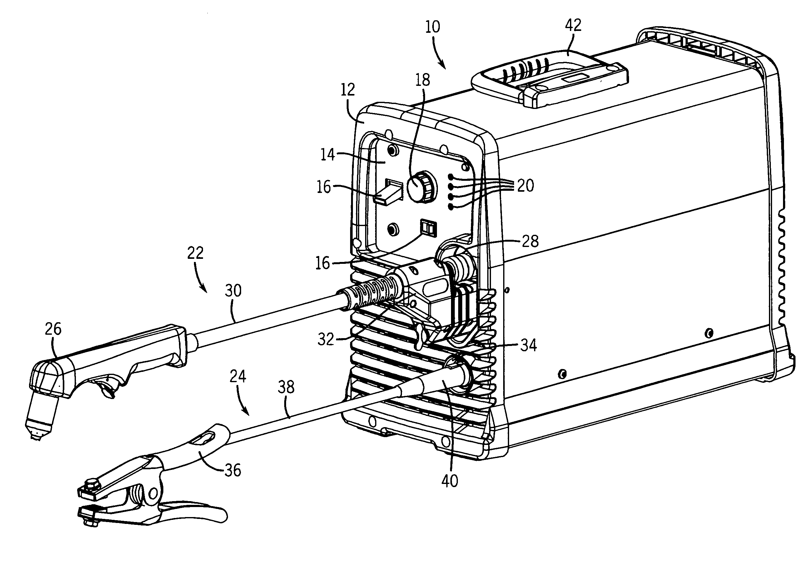
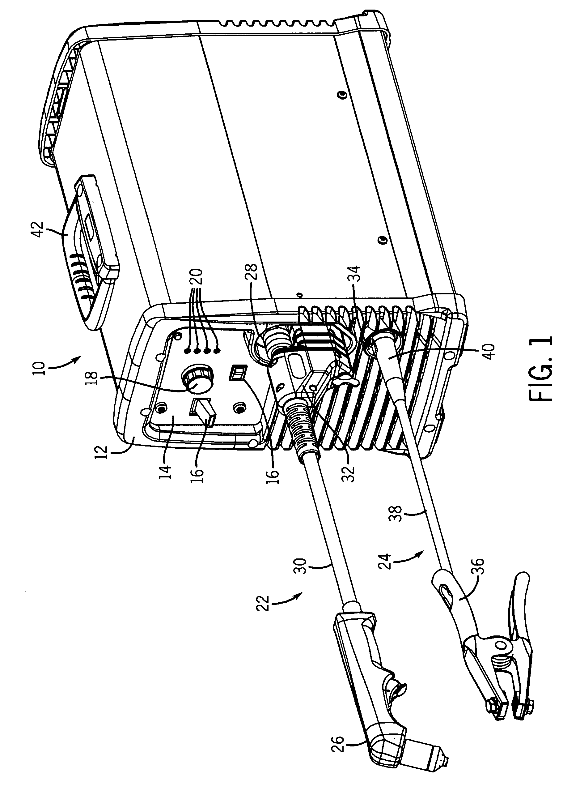
[0015]FIG. 1 illustrates an exemplary plasma cutting power supply 10, which functions to power and control a cutting operation in accordance with aspects of the present disclosure. An interface panel 12 on the front side of the power supply unit 10 in the illustrated embodiment contains a control panel 14, through which a user may control the supply of materials, such as power, gas flow, and so forth for a cutting operation, via switches 16, knobs 18, and so forth. Display 20 on the control panel 14 provide the user with information regarding operation of the power supply unit 10. A torch assembly 22 and a work lead assembly 24 communicatively couple with the power supply unit 10. The torch assembly 22 includes a cutting torch 26 that is communicatively coupled to a first port 28 in the power supply unit 10 via a first cable 30 and a first connector 32 of the torch assembly 22. A second port 34 facilitates coupling of the work lead assembly 24 with the power supply unit 10. Specific...


PUM

PropertyMeasurementUnit
temperatureaaaaaaaaaa
voltageaaaaaaaaaa
poweraaaaaaaaaa

Abstract

Systems and methods relating to securing a torch assembly and a work lead assembly to a plasma cutting power supply are provided. The present disclosure relates to a system and method that allows the torch assembly and the work lead assembly to be readily replaced by the user since the power supply unit need not be opened or disassembled for removal. The present disclosure provides methods and systems for removably securing both the torch assembly and the work lead assembly to the plasma cutting power supply. In one embodiment, the torch assembly and the work lead assembly may be communicatively coupled to the plasma cutting power supply unit via a single cable and a single connector. The connection between the first connector and the first port may be of the quick disconnectable type. The connection between the second connector and the second port may be of the twist lock type, such as a dinse style connector.

Description

CROSS REFERENCE TO RELATED APPLICATIONS[0001]This application is a U.S. Non-provisional Patent Application of U.S. Provisional Patent Application No. 61 / 052,045, entitled “Plasma Cutter with Disconnectable Torch and Work Cables”, filed May 9, 2008, which is herein incorporated by reference.BACKGROUND[0002]The present disclosure relates generally to plasma cutting systems, and more particularly, to methods and systems for removably connecting a plasma cutting torch and a work lead to a plasma cutting power supply unit.[0003]A plasma cutting system harnesses the energy in plasma (e.g., high temperature ionized gas) to cut metal or other electrically conductive material. A plasma arc must be struck between components in the plasma cutting torch and the work piece. This process requires a voltage output between the cutting torch and the workpiece. Accordingly, a power supply unit coupled to a torch and a work lead is an integral part of any plasma cutting system. Typical plasma cutting ...

Claims


Application Information

Patent Timeline
Patent Type & Authority Applications(United States)
IPC IPC(8): B23K10/00H05B3/02
CPCB23K9/013B23K9/323B23K10/00Y10T29/49826Y10T29/49083H05H1/34B23P19/00H05H1/3423
Inventor BORNEMANN, BRIAN JAMESLEITERITZ, NATHAN GERALD
Owner ILLINOIS TOOL WORKS INC
Why Eureka
Try Eureka