Method and system for a network of wireless ballast-powered controllers

a wireless ballast and controller technology, applied in the field can solve the problems of exceeding the cost of building operators, the cost necessary to install and/or maintain the significant cost of wireless building control systems, so as to reduce the light level and power consumption

Inactive Publication Date: 2009-11-12
MILLS JERRY +1
View PDF8 Cites 79 Cited by
  • Summary
  • Abstract
  • Description
  • Claims
  • Application Information

AI Technical Summary

Benefits of technology

[0005]Against this backdrop systems and methods have been developed for providing a network of wireless ballast-powered controllers. The wireless controllers (or wireless nodes) are connected to ballasts that provide the wireless controllers with power. The wireless controllers may be networked with other networkable controllers (including other wireless ballast-powered controllers), lighting ballasts, and other building-related devices, including but not limited to daylight harvesters and occupancy sensors. The wireless ballast-powered controllers may implement one or more wired or wireless data communication protocols, including but not limited to BACnet®, LonWorks®, or ZigBee® data communication protocols, and may include multiple inputs and outputs. The wireless ballast-powered controllers include control logic for delivering a control signal and / or power signal to one or more other networkable controllers, lighting ballasts, and / or other building-related ancillary devices. The network of wireless ballast-powered controllers may permit reduction of light levels and power consumption (e.g., using load-shedding applications) within a building.

Problems solved by technology

Despite improving the management of building controls, wireless building control systems typically require building operators to install separate power lines to each endpoint control device or continuously replace batteries within each of the endpoint control devices.
The cost necessary to install and / or maintain wireless building control systems may be significant and exceed the costs a building operator might otherwise incur to install and / or maintain a wired building control system.

Method used


Image

  • Method and system for a network of wireless ballast-powered controllers
  • Method and system for a network of wireless ballast-powered controllers
  • Method and system for a network of wireless ballast-powered controllers

Examples


Embodiment Construction

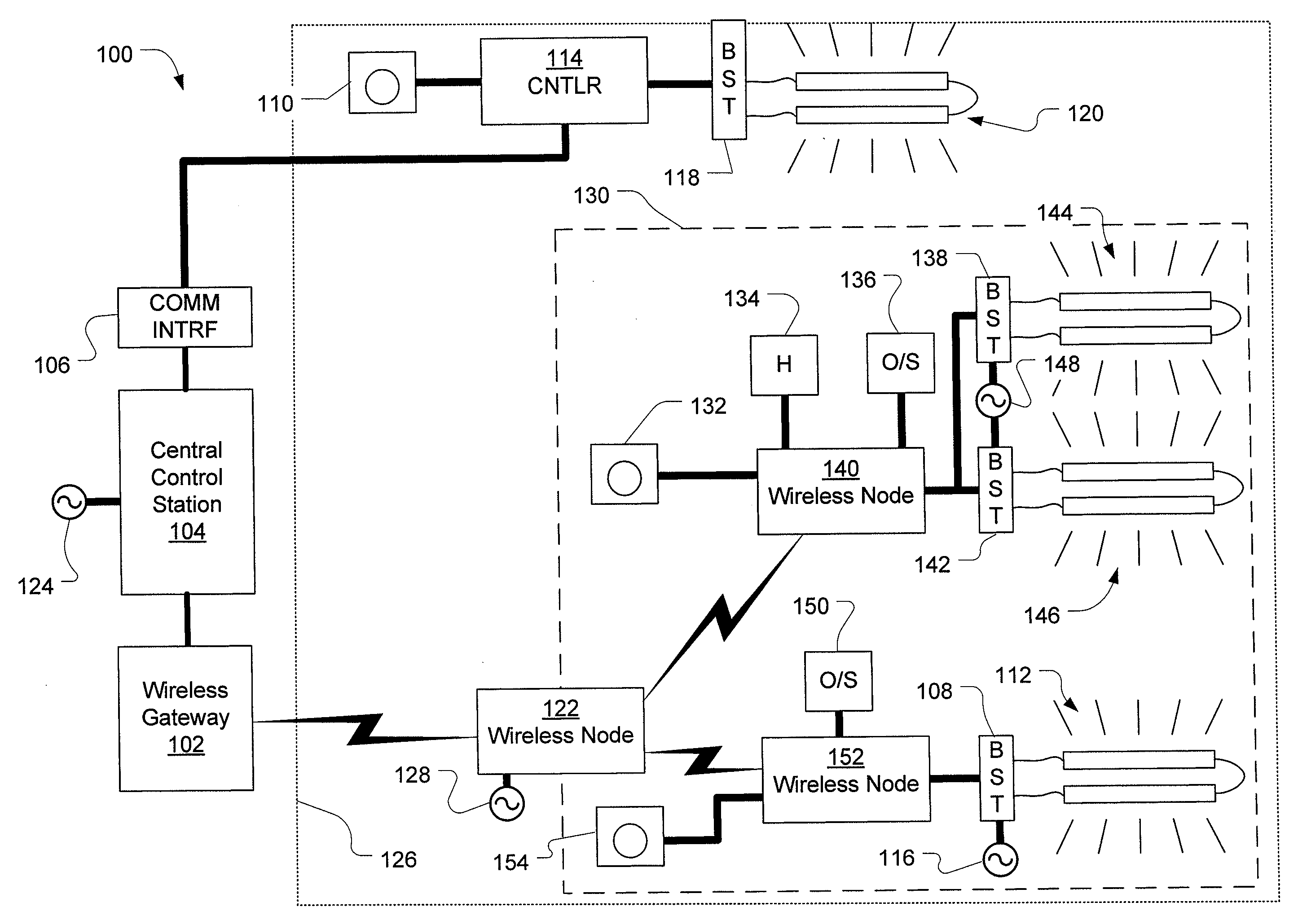
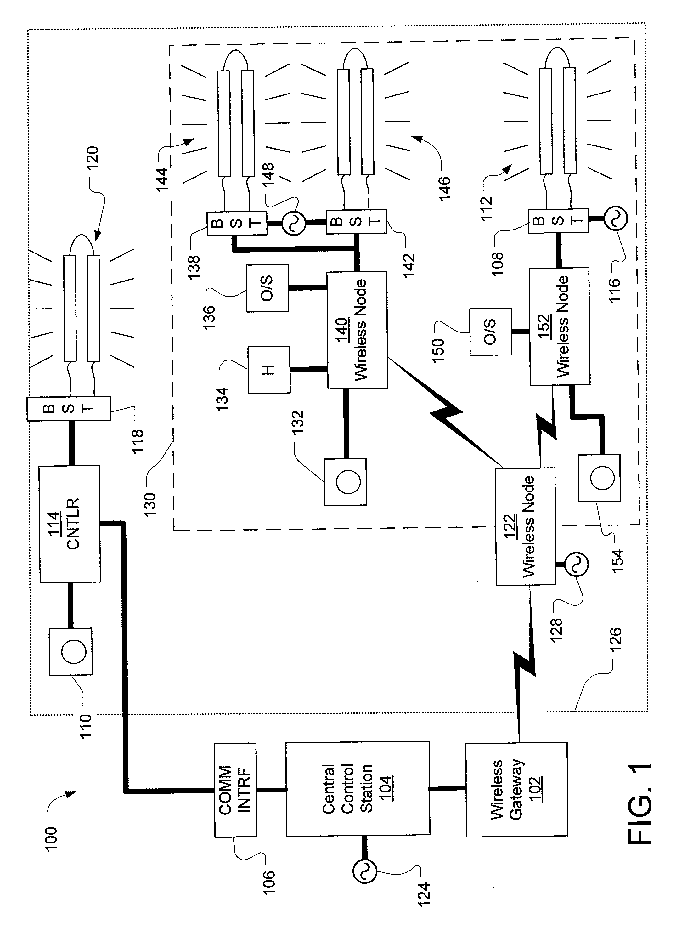
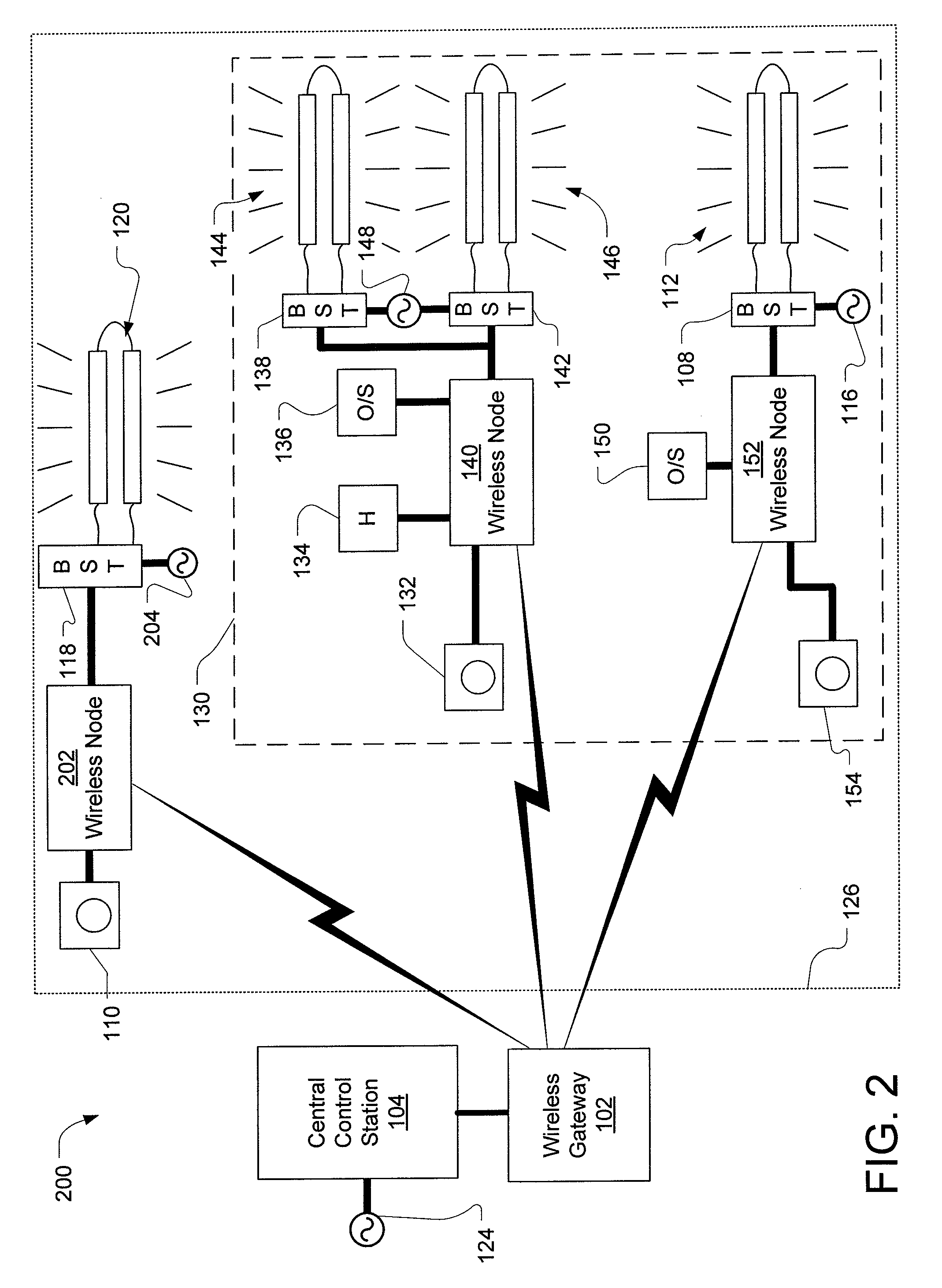
[0013]The following detailed description is intended to convey a thorough understanding of the embodiments described by providing a number of specific embodiments and details involving systems and methods for networking an autonomous lighting subsystem. It should be appreciated, however, that the claims appended hereto are not limited to these specific embodiments and details, which are exemplary only. It is further understood that one possessing ordinary skill in the art, in light of known systems and methods, would appreciate the applicability of this disclosure for its intended purposes and benefits in any number of alternative embodiments, depending upon specific design and other needs.

[0014]A wireless ballast-powered controller (also referred to as a “wireless node”) may be networked with other networkable wireless nodes, other power controllers (e.g., wired nodes), lighting ballasts, and user-controlled voltage selectors to provide a lighting control network. A wireless node m...


PUM


Abstract

Autonomous lighting subsystems include ballast-powered wireless nodes for receiving control signals to control lighting devices. Autonomous lighting subsystems may be networked with other autonomous lighting subsystems to control various building-devices, including but not limited to lighting ballasts, occupancy sensors, daylight harvesters, and building automation control devices.

Description

TECHNICAL FIELD[0001]The invention relates generally to wireless building control systems, and more particularly to a network of wireless ballast-powered controllers used to control electrical or electro-mechanical systems in buildings.BACKGROUND[0002]A building control system generally allows a building operator to control a building system within one or more buildings, such as an HVAC system (heating, ventilation, and air conditioning system), a lighting system, a water and waste system, or a security system. For example, a building control system may include a centralized or remote building control station from which a building operator may configure thermostat setting schedules and monitor temperatures in various building zones. In this manner, a building operator can manage energy use and tenant comfort in accordance with the anticipated building usage during various hours of the day.[0003]Various open systems standards for building control system networks, such as the BACnet® ...

Claims


Application Information

Patent Timeline
Patent Type & Authority Applications(United States)
IPC IPC(8): H05B41/36
CPCH05B37/0272H05B47/19
Inventor MILLS, JERRYEMPEY, BRIAN
Owner MILLS JERRY
Why Eureka
Try Eureka