
Directional coupler and a receiving or transmitting device

Active Publication Date: 2009-11-12
HUAWEI TECH CO LTD
View PDF7 Cites 1 Cited by
  • Summary
  • Abstract
  • Description
  • Claims
  • Application Information

AI Technical Summary

Benefits of technology

[0024]The embodiments of the present disclosure in comparison with existing directional couplers may have a low transmission loss, a large power capacity and a superior directivity index, guarantee a good PIM index, be assembled easily, have good consistency of indexes and be adapted to different application scenarios. The above directional coupler may guarantee various parameter indexes and be assembled easily at a low cost.

Problems solved by technology

For the metal rod coupler with the medium of air, relative positions of the two metal rods subject to an assembling precision thereof may further influence a coupling degree and a directivity index of the coupler, so that the assembled coupler may suffer from poor consistency of the directivity index and thus has to be connected to an external adjusting element.
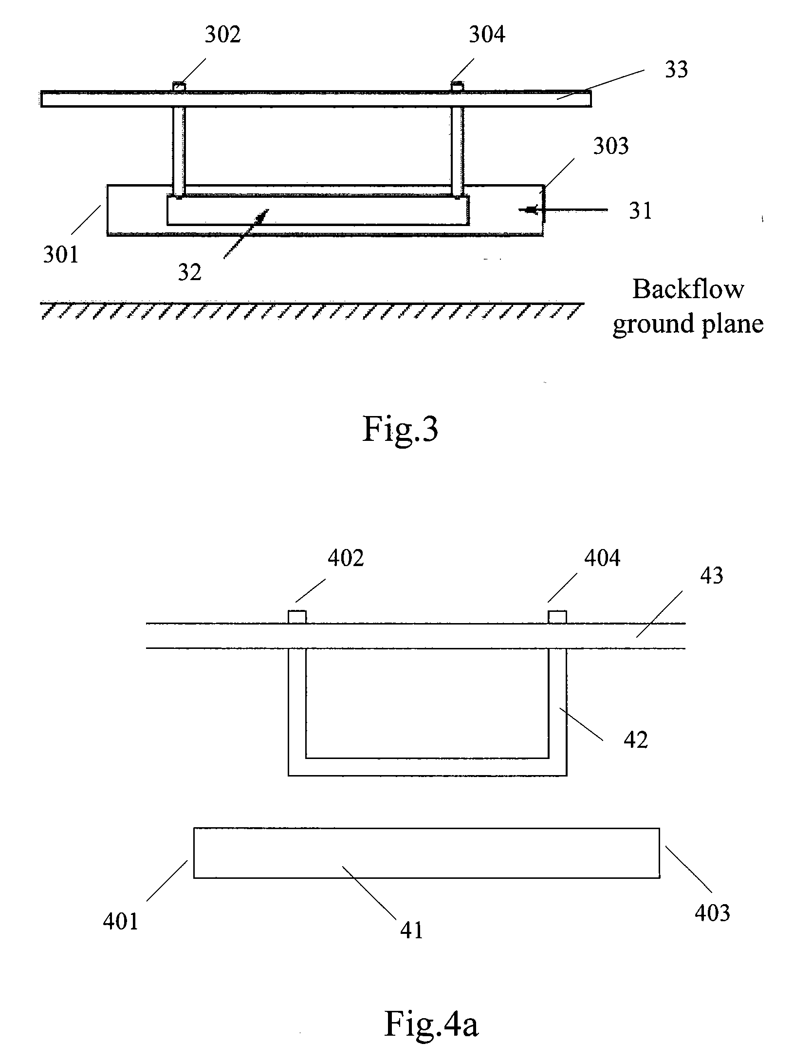
Regardless of the hanging wire leap-line coupler in FIG. 4a or the improved hanging wire leap-line coupler in FIG. 4, they enjoy a slightly superior directivity index to that in the first prior art but may still suffer from poor consistency of the directivity index due to an accumulative error of the assembling precision.
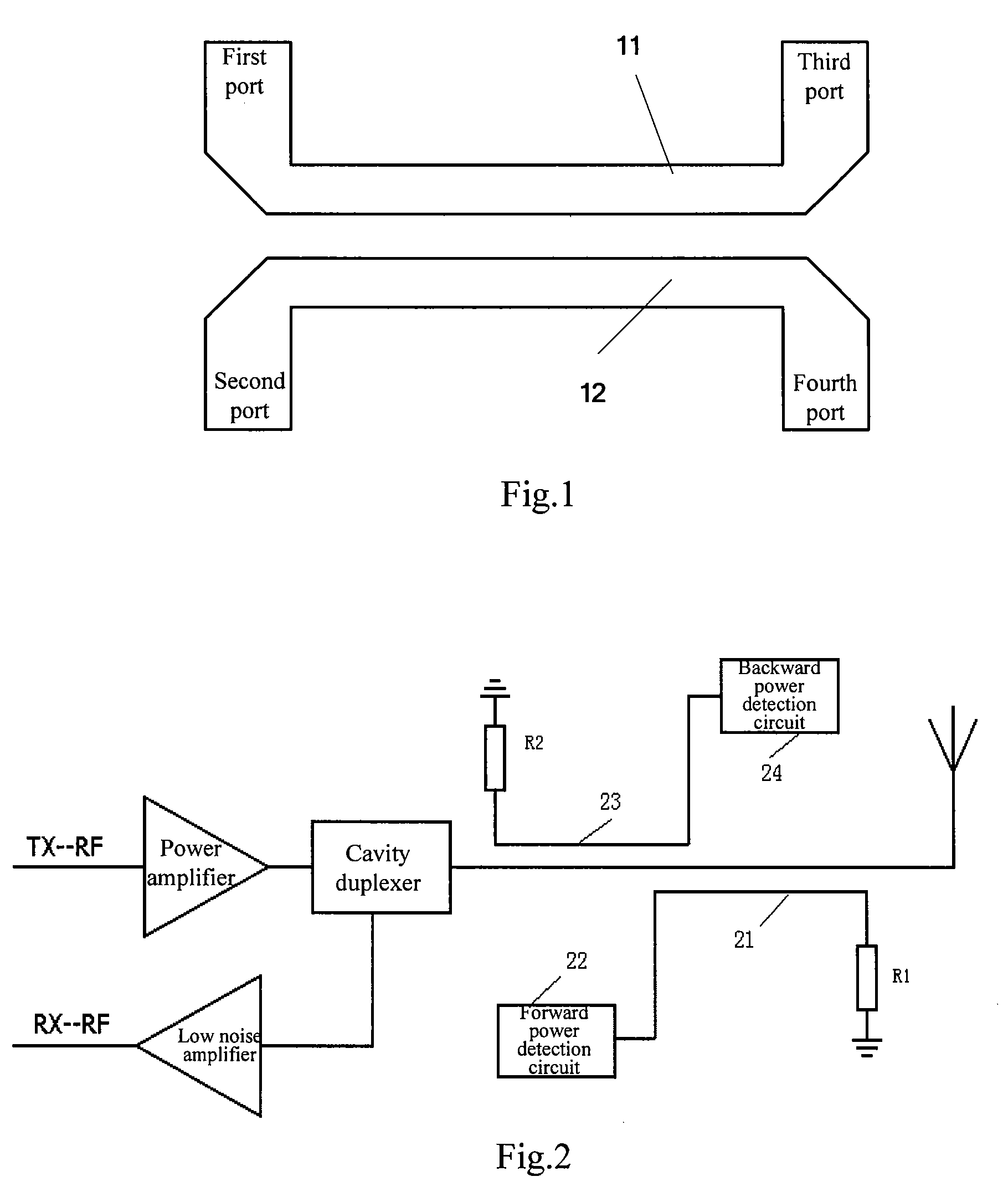
A primary signal line and a coupled signal line of a conventional strip directional coupler are composed of strips, and the coupler is arranged in a non-uniform medium and thus has a poor directivity index.
Further, the primary signal line of the coupler may suffer from a poor index of Passive Intermodulation (PIM) due to a large number of welding points.
The directional coupler structure in FIG. 7 has advantages of easy assembling and good consistency but may suffer from a poor directivity index of the coupler, approximately 15 dB or worse.
The fast odd mode and the slow even mode may result in the poor directivity index of the coupler, and an increase in the phrase velocity of the even mode may be impossible due to the structure of the coupler.
Summarily for above, the directional couplers in the prior art may not be satisfactory in terms of all the parameter indexes such as the directivity index, consistency of the directivity index, the PIM index, the power capacity index, etc., and one or more of the parameter indexes of the existing directional couplers have to be improved in the prior art with a demanding precision and a high cost.
Consequently, the parameter indexes of the existing directional couplers may not be improved effectively at a low cost.

Method used


Image

  • Directional coupler and a receiving or transmitting device
  • Directional coupler and a receiving or transmitting device
  • Directional coupler and a receiving or transmitting device

Examples


Embodiment Construction

[0037]Various embodiments of the disclosure are described in detail below with reference to the drawings.

[0038]According to an embodiment of the present disclosure, the phrase velocities of the odd and even modes are substantially equal by decreasing the phrase velocity of the odd mode, thereby improving the directivity index of the coupler.

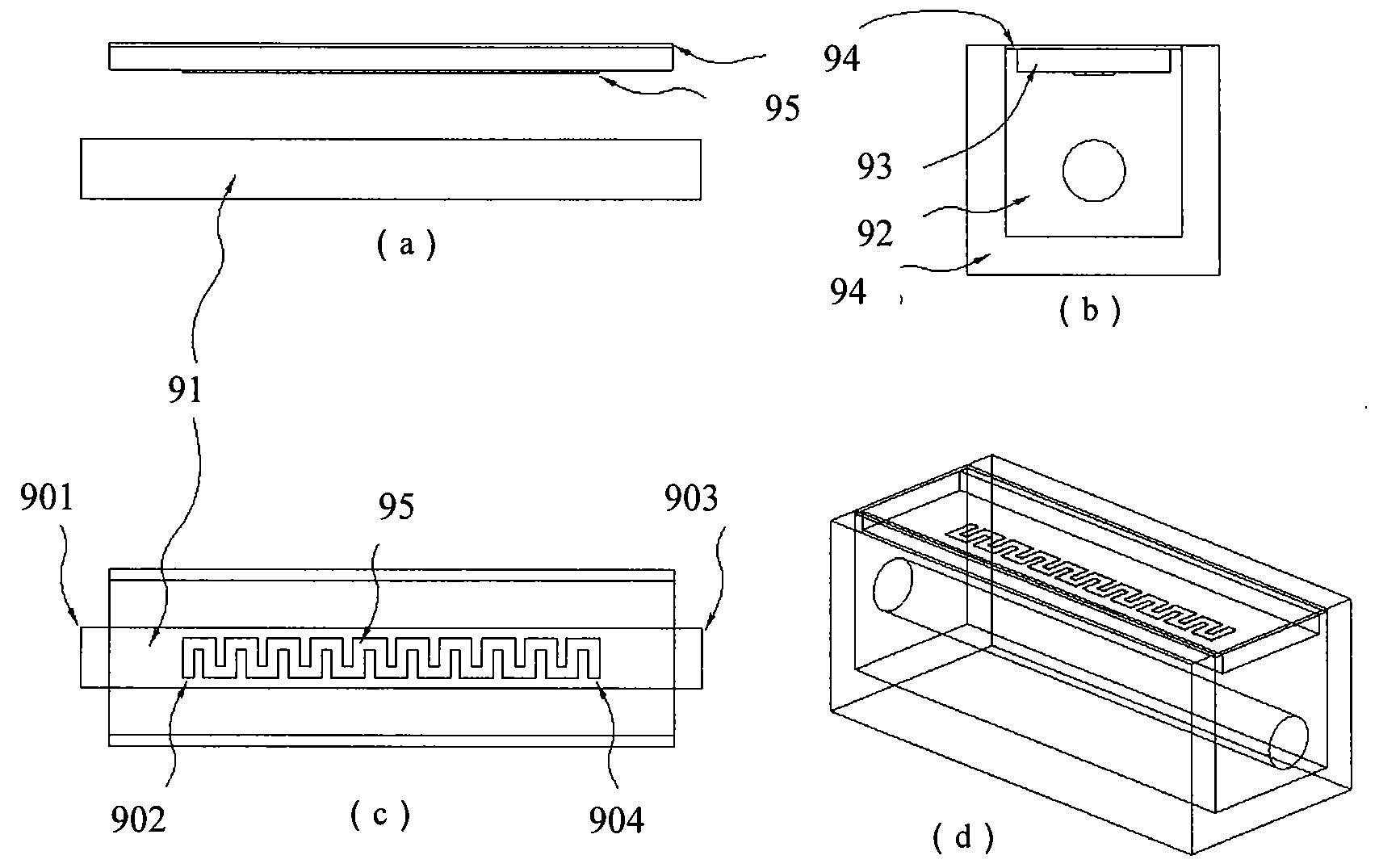
[0039]FIG. 8 illustrates a principle schematic diagram of a directional coupler according to an embodiment of the present disclosure. As shown in FIG. 8, the embodiment of the present disclosure makes a coupling micro strip curved (like a folded line or a smooth curve) so that a path along which the odd mode propagates runs down the curved micro strip, and thus the odd mode although propagating at the velocity of light may wriggle. Equivalently, the odd mode propagates in the direction of the primary signal line at a reduced phrase velocity.

[0040]The phrase velocities of the odd and even modes in the direction of the primary signal line may be ma...


PUM


Abstract

A directional coupler and a receiving or transmitting device. The directional coupler includes: a primary signal line composed of a metal rod; and a coupled signal line composed of a micro strip in a curved shape on a printed circuit board; wherein the medium between the metal rod and the micro strip is air. Compared with existing directional coupler, the directional coupler of the embodiments of the disclosure has a lower transmitting loss, a large power capacity, and a high directional qualification. The directional coupler is capable of ensuring a higher passive intermodulation qualification. The advantages of the embodiments of the present disclosure are easier assembly, good uniformity of the qualifications, and adaptability for various application environments. The directional coupler of the disclosure ensures different parameter qualifications, and is simple to assemble, so that the low cost is achieved.

Description

CROSS-REFERENCE TO RELATED APPLICATIONS[0001]This application is a continuation of International Patent Application No. PCT / CN2008 / 070031, filed on Jan. 7, 2008, which claims priority to Chinese Patent Application No. 200710062806.3, filed on Jan. 18, 2007, both of which are incorporated by reference herein their entireties.FIELD OF THE DISCLOSURE[0002]The present disclosure relates to the communication field and in particular to a directional coupler and a receiving or transmitting device.BACKGROUND OF THE DISCLOSURE[0003]Couplers are widely used in radio frequency and microwave systems to allocate and integrate signal power and to sample and detect power in a balance device of amplifier, phrase shifter, filter, etc. A typical coupler is actually a four-port network dividing an input signal in a specific frequency range into two output signals the power of which is in a specific ratio. There are numerous types of couplers with different natures including a coupling line directional...

Claims


Application Information

Patent Timeline
IPC IPC(8): H01P5/00
CPCH01P5/18H01P5/107
Inventor HE, PINGHUALI, XINLUCHEN, JIANJUNWEI, ZHAOLUJU, GANG
Owner HUAWEI TECH CO LTD
Learn More