
Composite multiplexer circuit and chip component, high-frequency module and radio communication apparatus using the same

Inactive Publication Date: 2005-12-22
KYOCERA CORP
View PDF7 Cites 49 Cited by
  • Summary
  • Abstract
  • Description
  • Claims
  • Application Information

AI Technical Summary

Benefits of technology

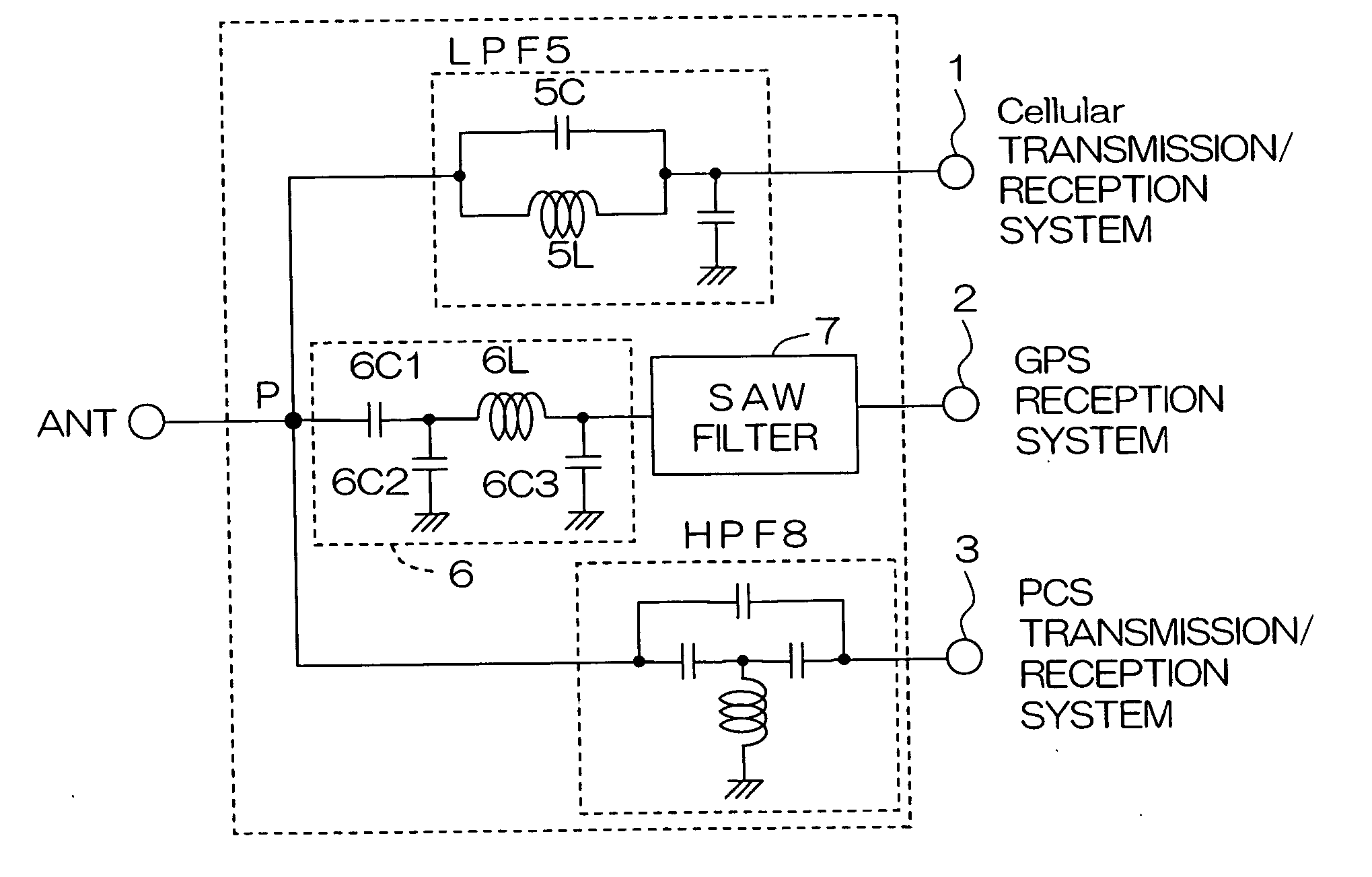
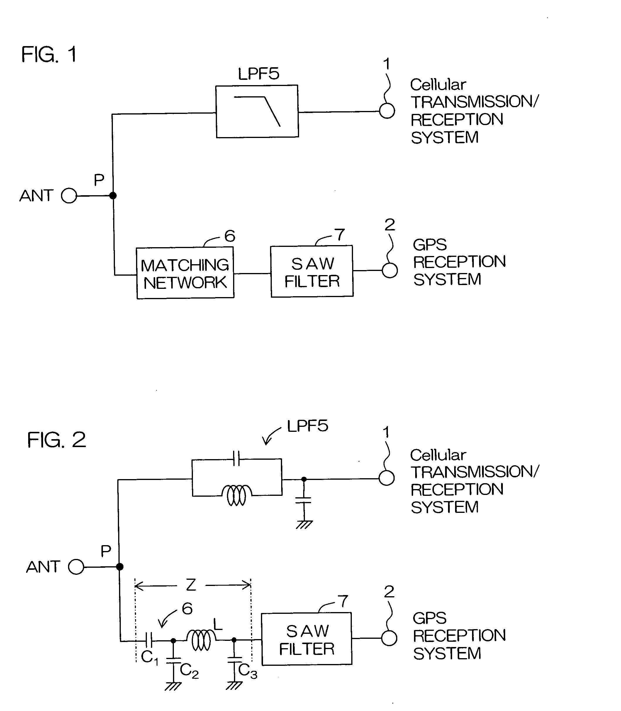
[0019] According to the configuration, the aforesaid multiplexer circuit for extracting one frequency band comprises the matching network and the surface acoustic wave filter connected in series with the matching network and may be set to have infinite impedance at the other frequency band than a frequency band thereof by selecting a constant for the matching network. This inhibits interference with the other multiplexer circuit for extracting a high-frequency signal in the other frequency band, thereby preventing the leakage of electric power.
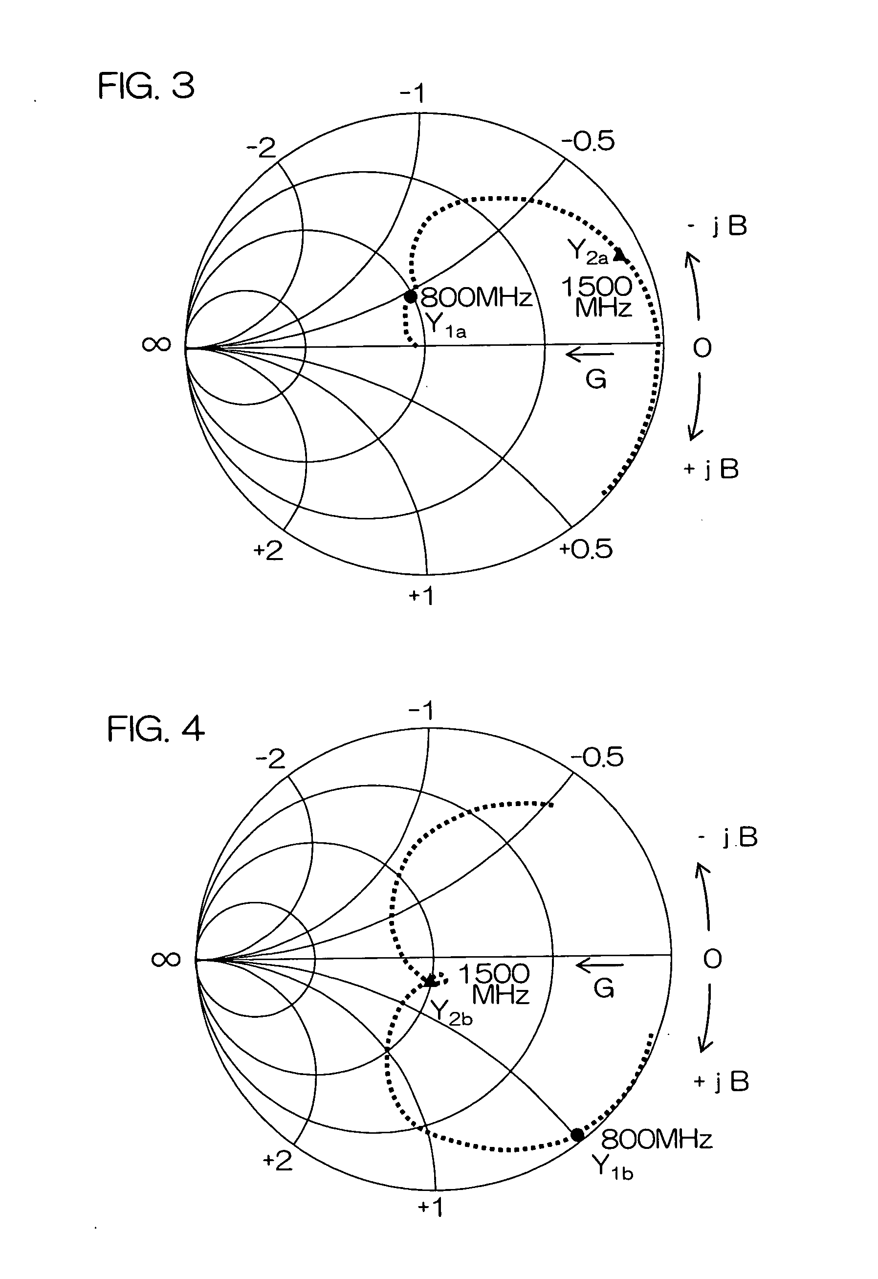
[0020] This composite multiplexer circuit may preferably establish a relation that the total sum of real parts of admittances in the individual frequency bands of all the multiplexer circuits, as viewed from a junction point connected with an antenna terminal, is 1 whereas the total sum of imaginary parts of the admittances thereof is 0, the admittances normalized by a characteristic admittance. So long as this relation is satisfied, there may be provided the composite multiplexer circuit which is adapted to meet plural frequency bands and suffers less transmission loss in any of the frequency bands.
[0024] The series inductor of the matching network may preferably have an Inductance L of 15 nH or less, and a Q-value (hereinafter referred to as “Q”) of 15 or more as determined at 800 MHz. By limiting the Inductance L and the Q to the above ranges, the multiplexer circuit of interest can be decreased in the transmission loss at the pass frequency thereof while maintaining the infinite impedances at the other frequencies.
[0027] According to this configuration, there may be provided the composite multiplexer circuit which is adapted to meet plural frequency bands and always connectable. The composite multiplexer circuit can be formed without using a switching device such as a diode and besides, does not suffer increased transmission losses. In a case where a SAW filter is connected rearwardly of the composite multiplexer circuit, the composite circuit is capable of reducing static electricity affecting the SAW filter and suppressing harmonic distortion, and does not require an increased number of components.
[0028] It is desirable that the composite multiplexer circuit establishes a relation that the total sum of real parts of admittances in the individual frequency bands of all the multiplexer circuits, as viewed from a junction point connected with an antenna terminal, is 1 whereas the total sum of imaginary parts of the admittances thereof is 0, the admittances normalized by a characteristic admittance. So long as the relation is satisfied, there may be provided the composite multiplexer circuit which is adapted to meet plural frequency bands and suffers less transmission loss in any of the frequency bands.
[0033] According to the invention, a compact high-frequency module having an excellent electrical transmission performance may be provided, which comprises the aforementioned composite multiplexer circuit mounted on a surface of and / or internally of a dielectric multilayered substrate, and which mounts thereon either one or both of a duplexer and a power amplifier.

Problems solved by technology

In actual fact, however, the input impedances in these frequency bands are significantly low.

Method used


Image

  • Composite multiplexer circuit and chip component, high-frequency module and radio communication apparatus using the same
  • Composite multiplexer circuit and chip component, high-frequency module and radio communication apparatus using the same
  • Composite multiplexer circuit and chip component, high-frequency module and radio communication apparatus using the same

Examples


Embodiment Construction

[0070] Preferred embodiments of the invention will hereinbelow be described in details with reference to the accompanying drawings.

[0071]FIG. 1 is a block diagram showing a composite multiplexer circuit according to the invention. FIG. 2 is a circuit diagram of the above composite multiplexer circuit.

[0072] The composite multiplexer circuit has a dual band configuration corresponding to two communication systems which include, for example, the Cellular communication system (a first frequency band: 800 MHz) and the GPS communication system (a second frequency band: 1500 MHz).

[0073] The composite multiplexer circuit includes: an ANT terminal connected with an antenna; a first terminal 1 for input / output of high-frequency signals in the first frequency band; and a second terminal 2 for input of a high-frequency signal in the second frequency band.

[0074] A low-pass filter circuit (hereinafter referred to as “LPF”) 5 is connected between the ANT terminal and the first terminal 1. As ...


PUM


Abstract

In a composite multiplexer circuit designed to multiplex plural frequency bands by interconnecting plural multiplexer circuits in parallel, a multiplexer circuit for extracting a frequency band of a GPS reception system includes a matching network including an inductor and a capacitor, and a surface acoustic wave filter connected in series with the matching network. The multiplexer circuit for the GPS reception system can be so set as to have infinite impedances at the other frequency bands than the frequency band thereof. This prevents signals in the other frequency bands from leaking into the multiplexer circuit for the GPS reception system.

Description

BACKGROUND OF THE INVENTION [0001] 1. Field of the Inveniton [0002] The present invention relates to a composite multiplexer circuit capable of multiplexing high-frequency signals in plural different frequency bands, and to a chip component, high-frequency module and radio communication apparatus using the same. [0003] 2. Description of the Related Art [0004] Portable telephones have been spreading wider and wider in recent years, while the function of the portable telephones and the services associated therewith have been improved. [0005] A multiband portable telephone has been proposed as a novel portable telephone. In contrast to the conventional portable telephones handling only one transmission / reception system, the multiband portable telephone is adapted to handle a plurality of transmission / reception systems. This permits a user to selectively use any one of the transmission / reception systems that is suited for a service area or usage purpose. [0006] In another practice, a re...

Claims


Application Information

Patent Timeline
IPC IPC(8): H04B1/40H03H7/46H03H9/70H03H9/72H04B1/04H04B1/06H04B1/16H04B1/56
CPCH03H7/463H03H9/0576H04B1/18H03H9/725H04B1/0057H03H9/72H03H7/46H04B1/40
Inventor MAKINO, YUTAKA
Owner KYOCERA CORP
Learn More