Phased array antenna

a phased array and antenna technology, applied in the direction of waveguide devices, resonant antennas, substantially flat resonant elements, etc., can solve the problem of difficult to obtain a symmetrical beam shape, and achieve the effect of high directional gain

Inactive Publication Date: 2009-11-12
PANASONIC CORP
View PDF3 Cites 67 Cited by
  • Summary
  • Abstract
  • Description
  • Claims
  • Application Information

AI Technical Summary

Benefits of technology

[0130]According to the present invention, when a phased array antenna having variable phase shifters constituted by using a variable dielectric-constant dielectric substance whose dielectric constant varies according to an applied electric field is constituted such that a group of the variable phase shifters for right-side tilt and a group of the variable phase shifters for left-side tilt can be controlled for their phase shift amounts independently from each other in order to realize a high directional gain, a DC blocking element for dc-wise separating two bias voltages, which causes mismatching, can be dispensed with, thereby realizing an antenna which can maintain a high directional gain with less deformation of the beam shape even when beam tilt occurs.
[0131]Further, according to the present invention, in a phased array antenna having variable phase shifters constituted by using a variable dielectric-constant dielectric substance whose dielectric constant varies according to an applied voltage, since a liquid crystal or a complex material including a liquid crystal is injected as a variable dielectric-constant dielectric layer constituting each variable phase shifter of the phased array antenna by a vacuum injection method or a capillary injection method, the liquid crystal or the complex material including a liquid crystal can be uniformly injected into a liquid crystal container to be the variable dielectric-constant dielectric layer, thereby realizing a phased array antenna which can reduce variations in the dielectric constant of the variable dielectric-constant dielectric layer, and maintain a high directional gain with less deformation of the beam shape even when beam tilt occurs.

Problems solved by technology

Further, since each variable phase shifter has a dielectric loss, an insertion loss due to a conductor loss, and a reflection loss due to mismatching, the electric powers distributed to the respective antenna elements and the phases undesirably vary, resulting in a difficulty in obtaining a symmetrical beam shape.

Method used


Image

  • Phased array antenna
  • Phased array antenna
  • Phased array antenna

Examples


embodiment 1

Embodiment 1

[0350]Initially, a description will be given of an embodiment of a phased array antenna of the present invention which adopts a solid dielectric material as a variable dielectric-constant dielectric layer.

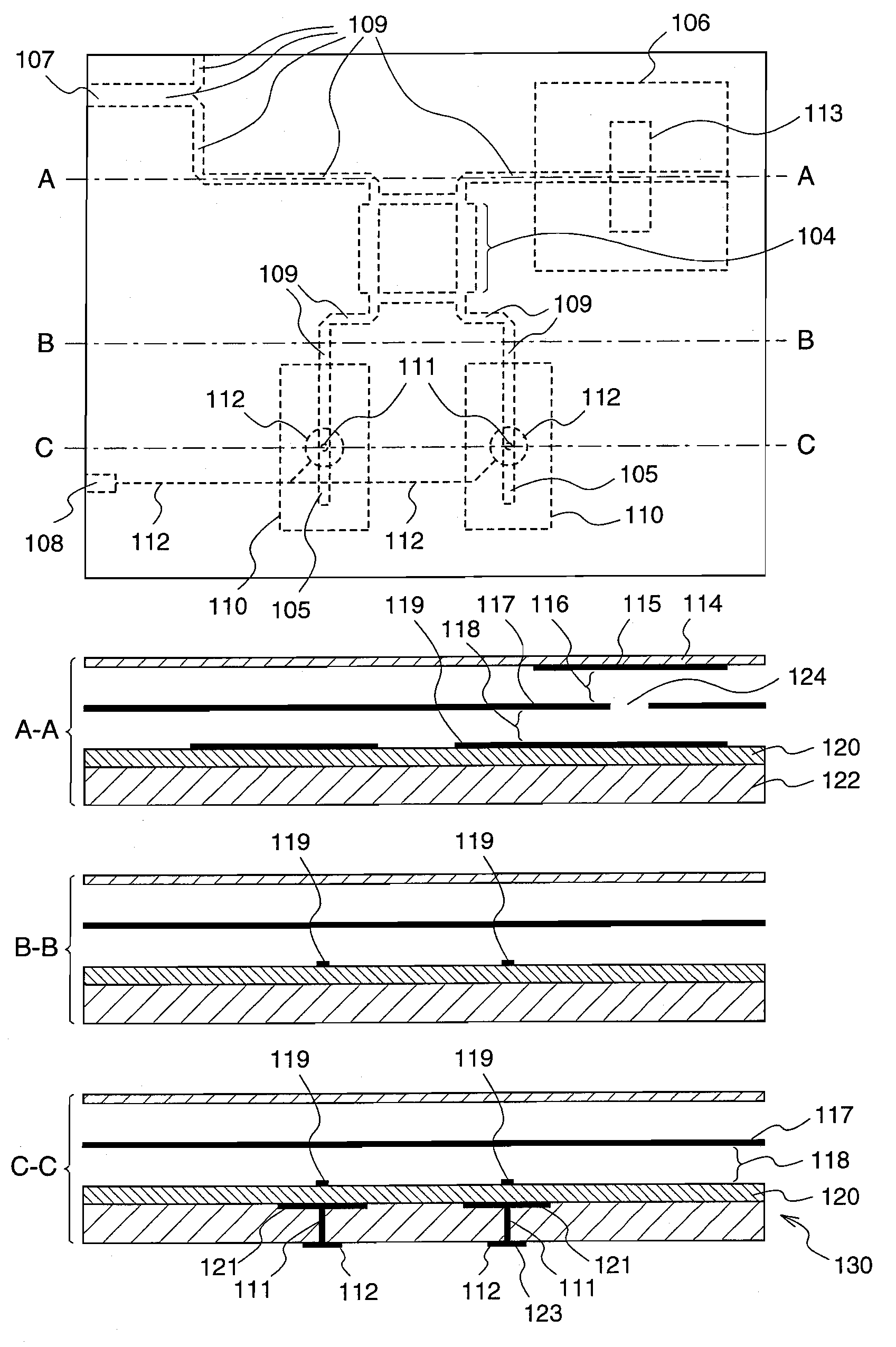
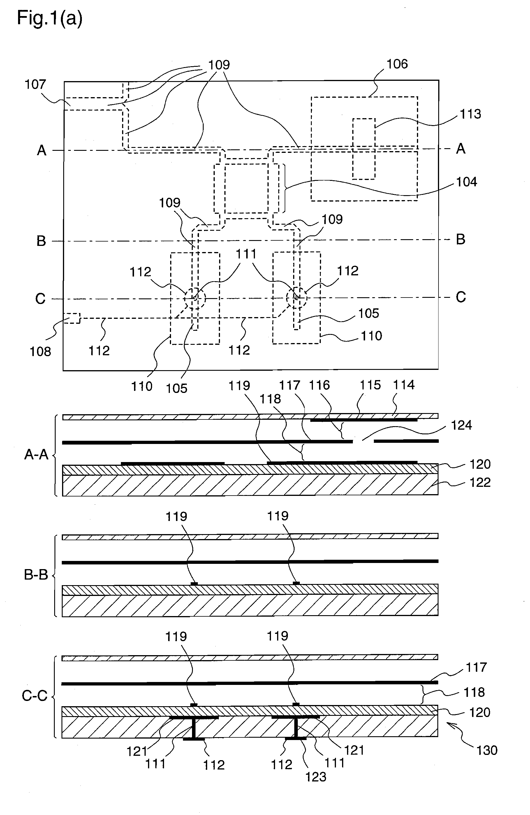
[0351]FIG. 1(a) illustrates a plan view and cross-sectional views of a phased array antenna according to the first embodiment of the present invention.

[0352]In FIG. 1(a), a diagram positioned at the top is a plan view of the antenna viewed from the radiation plane side. Subsequently, a A-A cross-sectional view, a B-B cross-sectional view, and a C-C cross-sectional view showing the states of cross sections obtained when the antenna is cut along a A-A line, a B-B line, and a C-C line in the plan view, respectively, are illustrated toward the bottom in the figure.

[0353]The display area of the plan view is identical to that of the conventional antenna shown in FIG. 7.

[0354]Further, in the plan view, a pattern of a hybrid coupler 104 and a pattern of a propagation characteri...

embodiment 2

Embodiment 2

[0379]Next, a description will be given of an embodiment of a phased array antenna of the present invention which adopts a liquid dielectric material such as a liquid crystal for a variable dielectric-constant dielectric layer.

[0380]FIG. 2(a) illustrates a plan view and cross-sectional views of a phased array antenna according to the second embodiment of the present invention.

[0381]In FIG. 2(a), a diagram positioned at the top is a plan view of the antenna viewed from the radiation plane side. Subsequently, a A-A cross-sectional view, a B-B cross-sectional view, and a C-C cross-sectional view showing the states of cross sections obtained when the antenna is cut along a A-A line, a B-B line, and a C-C line in the plan view, respectively, are illustrated toward the bottom in the figure.

[0382]The display area of the plan view is identical to that of the conventional antenna shown in FIG. 7.

[0383]Further, in the plan view, a pattern of a hybrid coupler 204 and a pattern of a...

embodiment 3

Embodiment 3

[0410]Next, a description will be given of an embodiment of a phased array antenna of the present invention which is constituted by providing a phased array antenna having a laminated layer structure, and then forming a variable dielectric-constant dielectric layer by uniformly injecting a liquid crystal or a material containing a liquid crystal into the structure.

[0411]FIG. 10 is a plan view illustrating an example of a phased array antenna according to a third embodiment of the present invention. In FIG. 10, the phased array antenna comprises a laminated structure of a feeding phase shift unit 308 and an antenna unit 309.

[0412]The feeding phase shift unit 308 comprises feeding ports 301, variable phase shifters 302 each including two propagation characteristic variable lines 115 which are disposed approximately parallel to each other as shown in FIG. 11, variable phase shifters 303 each including two propagation characteristic variable lines 115 which are disposed on a...


PUM


Abstract

There is provided a phased array antenna having variable phase shifters constituted by using a variable dielectric-constant dielectric substance whose dielectric constant varies according to an applied electric field, which antenna can dispense with a DC blocking element that causes mismatch, and reduce deformation of the beam shape even when beam tilt occurs, in the case where the variable phase shifters are divided into those for right-side tilt and those for left-side tilt and the phase shift amounts thereof are independently controlled.The phased array antenna is provided with a feeding phase shift unit (130) having a laminated structure obtained by laminating at least a ground conductor layer (117), an insulator layer (118), a main conductor layer (119), a variable dielectric-constant dielectric layer (120), and a sub conductor layer (121) in this order, and a propagation characteristic variable line (105) having a line on the sub conductor layer in an area which planarly overlaps a line on the main conductor layer is provided on the feeding phase shift unit. By applying a bias voltage between the main conductor layer and the sub conductor layer, the dielectric constant of the variable dielectric-constant dielectric substance in the propagation characteristic variable line area is varied to control the propagation characteristics. Thereby, a DC blocking element to be inserted in series into the feeding line can be dispensed with.

Description

TECHNICAL FIELD[0001]The present invention relates to a phased array antenna. More specifically, the invention relates to a technique for realizing a phased array antenna having variable phase shifters constituted by using a variable dielectric-constant dielectric substance whose dielectric constant varies according to an applied electric field, which can maintain a high directional gain with less deformation of beam shape even when beam tilt occurs.BACKGROUND ART[0002]1) Initially, a first background art will be described[0003]As a conventional phased array antenna having variable phase shifters constituted by using a variable dielectric-constant dielectric substance whose dielectric constant varies according to an applied electric field, there is a phased array antenna constructed such that variable phase shifters are divided into two groups for right-side tilt and left-side tilt, and the phase shift amounts thereof are independently controlled to reduce variations in the electric...

Claims


Application Information

Patent Timeline
Patent Type & Authority Applications(United States)
IPC IPC(8): H01Q1/38
CPCH01P1/184H01Q21/0093H01Q9/045H01Q3/34
Inventor KIRINO, HIDEKIHIRANAKA, KOUICHIHATAKEYAMA, TAKESHI
Owner PANASONIC CORP
Why Eureka
Try Eureka