
Directional diagram reconstructable microstrip aerial having Koch form-dividing paster

A technology of microstrip antenna and pattern, which is applied in the electronic field, can solve the problems of limited pattern gain and failure to scan the antenna pattern, and achieve the effect of high practical value, light weight and high gain

Inactive Publication Date: 2010-05-12
UNIV OF ELECTRONICS SCI & TECH OF CHINA
View PDF5 Cites 0 Cited by
  • Summary
  • Abstract
  • Description
  • Claims
  • Application Information

AI Technical Summary

Problems solved by technology

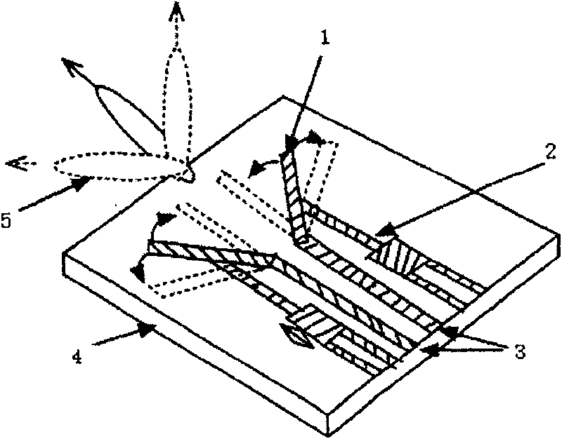
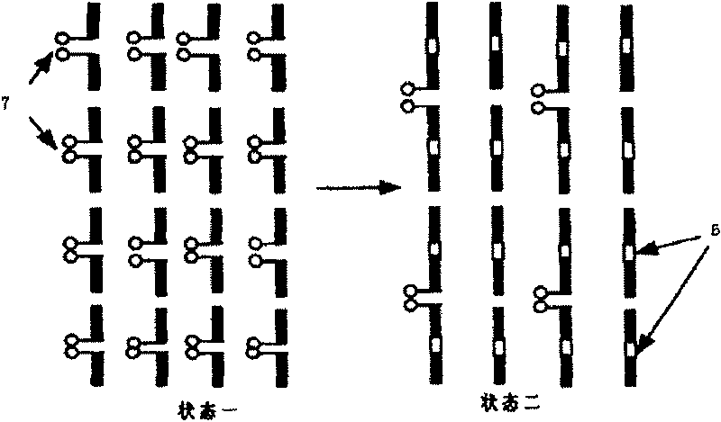
However, the scan of the antenna pattern cannot be realized on a frequency point (see figure 2 )
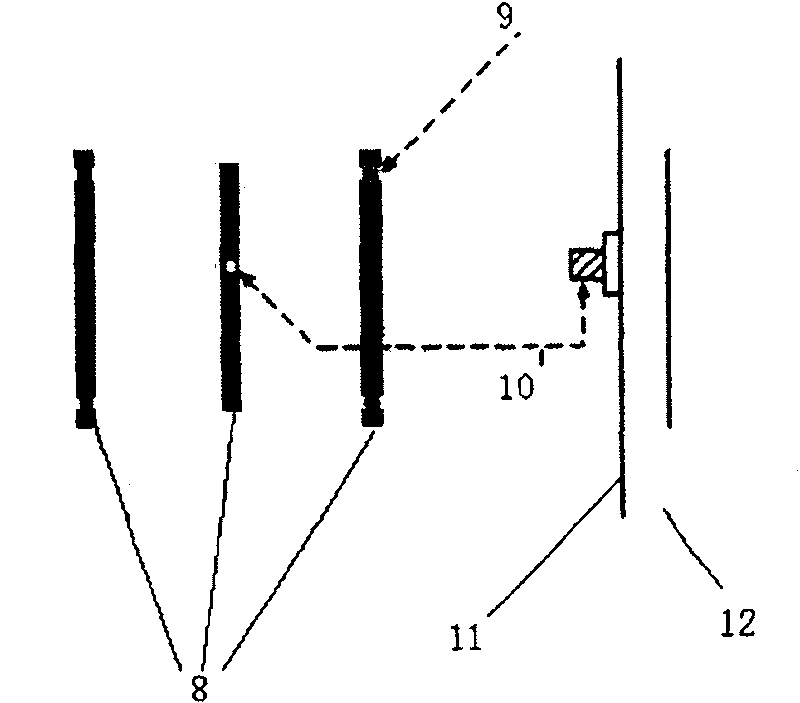
[0005] Although the document "A Pattern Reconfigurable Microstrip Parasitic Array" (IEEE Transactions On AntennaAnd Propagation, Vol:52, NO.10, October 2004) can realize pattern scanning at one frequency point, the gain of the pattern is limited, below 9dBi (see image 3 )

Method used


Image

  • Directional diagram reconstructable microstrip aerial having Koch form-dividing paster
  • Directional diagram reconstructable microstrip aerial having Koch form-dividing paster
  • Directional diagram reconstructable microstrip aerial having Koch form-dividing paster

Examples


Embodiment Construction

[0022] exist Figure 8 , 9 In the embodiment, the materials and properties of the antenna are: the dielectric substrate adopts a common composite dielectric substrate with a dielectric constant of 3.02, the metal floor and the Koch fractal metal patch adopt a copper foil with a thickness of 0.018mm, and the size of the metal floor is 400×400mm 2 , The Koch fractal metal patch is a third-order Koch fractal, the size of the six slots is 1mm×40mm, and they are symmetrically arranged around the floor at a distance of 45mm from the feeding point. The six short-circuit columns have a radius of 1 mm and are symmetrically arranged on a circle 23 mm away from the feeding center. The size of the planar package switch selected on the microstrip patch gap is 1×8mm 2 , the top of each short-circuit column is connected with a switch connected to the microstrip patch, the size is 1×2×2mm 3 .

[0023] The switch in one of the slits is connected to the switch of the opposite short-circuit...


PUM


Abstract

This invention relates to Koch sticking pad direction pattern re-form micro band antenna in electron technique, wherein, meal board 14 and three degree Koch distribution metal pad 15 are connected through co-axis; six short columns 17 pairs of symmetric small circles with detector 13 as center with its down end connected to metal board and top end connected to the sticking pad 15 through electronswitch; metal board 14 is opened with six same beam 19 with symmetrically distributed with large circle and at least one electron switch 18.

Description

technical field [0001] The invention belongs to the field of electronic technology, and relates to the technology of reconfigurable antenna with pattern. Background technique [0002] With the rapid development of wireless communication, high-performance compact reconfigurable antennas are more and more important for improving the performance of the overall communication system. On the one hand, the pattern reconfigurable antenna can reduce the electronic noise interference of the communication system and improve the stability of the system, and on the other hand, it can improve the communication efficiency of the antenna. However, the problems existing in the design of the existing pattern reconfigurable antenna restrict its further promotion and application in the market. [0003] The document "MEMS Reconfigurable Vee Antenna" (Microwave Symposium Digest, 1999IEEEMTT-S International, Volume: 4, 13-19 June) describes a structurally reconfigurable antenna (see figure 1 ), ...

Claims


Application Information

Patent Timeline
Patent Type & Authority Patents(China)
IPC IPC(8): H01Q13/00H01Q13/08H01Q13/10H01Q1/38
Inventor 王秉中刘会来肖绍球
Owner UNIV OF ELECTRONICS SCI & TECH OF CHINA
Learn More