Beamforming method and wireless device

A beamforming, wireless device technology, applied in the field of transceiver architecture, can solve the problems of high data rate processing, high complexity, high power consumption, etc., and achieve the effects of high directional gain, low complexity, and reduced complexity

Active Publication Date: 2020-07-21
MEDIATEK INC
View PDF4 Cites 0 Cited by
  • Summary
  • Abstract
  • Description
  • Claims
  • Application Information

AI Technical Summary

Problems solved by technology

Requires multiple RF chains (NA antennas require NA RF chains), which leads to high complexity
[0007] Find a solution to the high data rate processing and high power consumption in digital beamforming, and the high overhead of switching beam switching times in analog or hybrid beamforming

Method used


Image

  • Beamforming method and wireless device
  • Beamforming method and wireless device
  • Beamforming method and wireless device

Examples


Embodiment Construction

[0025] Some embodiments of the invention will now be described in detail, some examples of which are illustrated in the accompanying drawings.

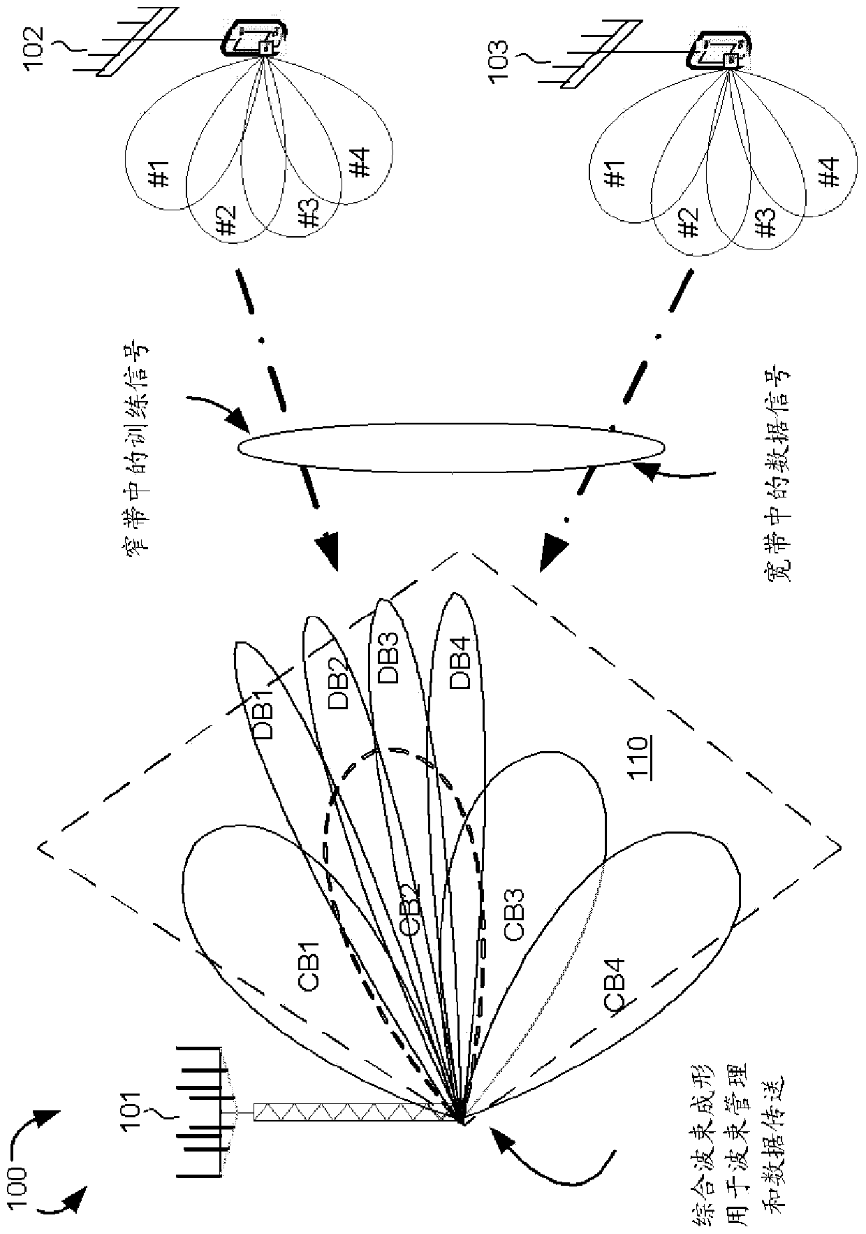
[0026] figure 1 is a combined schematic diagram of digital beamforming for beam training and analog / hybrid beamforming for data transmission in a beamforming mmWave cellular network 100 in accordance with one novel aspect. The beamforming mmWave cellular network 100 comprises a base station BS 101 , a first user equipment UE 102 and a second user equipment UE 103 . The beamforming mmWave cellular network 100 uses narrow beams for directional communications and can support multi-gigabit data rates. Directional communication is achieved by digital (adaptive) and / or analog (switched) beamforming, where multiple antenna elements apply multiple sets of beamforming weights (phaser values) to form multiple beam patterns. exist figure 1 In the example shown, the BS 101 is directed to configure multiple cells, each covered by a coarse TX / ...


PUM


Abstract

The invention proposes a beamforming method and a wireless device. Digital beamforming is used for beam training with reduced overhead (handover time) while facilitating the estimation of the angle of arrival of all user equipments. Additionally, the pilot / training signals are sent in a narrowband, which reduces complexity. Analog / hybrid beamforming is used for data transmission with high directional gain and low complexity. The values ​​of the beamforming weights (phaser values) in the analog domain may be based on the angles of arrival estimated in beam training. By employing digital beamforming for beam training, plus analog / hybrid beamforming for data transmission, efficient beamforming with reduced overhead, complexity and cost can be achieved.

Description

[0001] cross reference [0002] This application claims priority under 35 U.S.C. §119 to U.S. Provisional Application 62 / 080,626, filed November 17, 2014, entitled "Transceiver Architecture for Multiple Antenna Systems," which application is incorporated by reference. technical field [0003] The present invention relates to wireless communications, and more particularly to transceiver architectures with integrated beamforming in multi-antenna systems. Background technique [0004] In next-generation broadband cellular communication networks, the increasing shortage of mobile carrier bandwidth promotes the exploration of the underutilized millimeter wave (Millimeter Wave, mmWave) spectrum between 30G and 300GHz. The available spectrum in the mmWave band is two hundred times larger than that of conventional cellular systems. mmWave wireless networks use narrow beams for directional communications and can support multi-gigabit data rates. The bandwidth of the underutilized ...

Claims


Application Information

Patent Timeline
Patent Type & Authority Patents(China)
IPC IPC(8): H04B7/04H04B7/06H04B7/08H04W16/28
CPCH04B7/04H04B7/0619H04B7/0695
Inventor 陈儒雅詹景宏
Owner MEDIATEK INC
Why Eureka
Try Eureka