Acdc converter

a converter and converter technology, applied in the direction of electric variable regulation, process and machine control, instruments, etc., can solve the problems of completely suitable acdc converters for providing low no-load power consumption and high output efficiency, and achieve the effect of compact transformers, relative economic and cost-effective production

Active Publication Date: 2009-11-12
TEXAS INSTR INC
View PDF6 Cites 17 Cited by
  • Summary
  • Abstract
  • Description
  • Claims
  • Application Information

AI Technical Summary

Benefits of technology

[0003]Furthermore, by operating the power converter at increased efficiency, the power converter is able to operate within a given set of energy conservation standards and is able to minimise heat generation in the power converter. This has the direct effect of reducing the requirement for cooling fluids such as air or water to be used in conjunction with the power converter. In addition to the requirements of high efficiency and lower no-load standby power losses, ACDC converters typically require some measure of power factor correction to essentially bring the input current waveform as close as possible to a sinusoidal waveform, in phase with the input voltage. The power converters will also often have to be capable of operating in dual mode, handling nominally sinusoidal mains / line voltages spanning Japanese low line requirements of approximately 100V through to European high line requirements of approximately 220 to 240V.
[0028]In another embodiment of the invention there is provided a transformer for an ACDC converter in which there is provided a primary winding, a pair of dual function primary auxiliary bias supply windings and clamping primary windings, a pair of secondary power windings and a pair of drive windings. In this way, the transformer will have seven windings in total. Further additional primary windings could be provided if necessary. The transformer with the pair of auxiliary bias supply / clamping windings, the pair of drive windings and the pair of power windings will provide an excellent transformer design for the design of ACDC converter presented. This transformer will be both compact and efficient in use and will allow for flexible operation of the ACDC converter.

Problems solved by technology

However, there are problems associated with each of the known types of ACDC power converters and heretofore none of these ACDC converters has proven to be entirely suitable for providing low no-load power consumption with high output efficiency.

Method used


Image

  • Acdc converter
  • Acdc converter
  • Acdc converter

Examples


Embodiment Construction

[0029]The invention will now be more clearly understood from the following description of some embodiments thereof giving by way of example only with reference to the accompanying drawings in which:

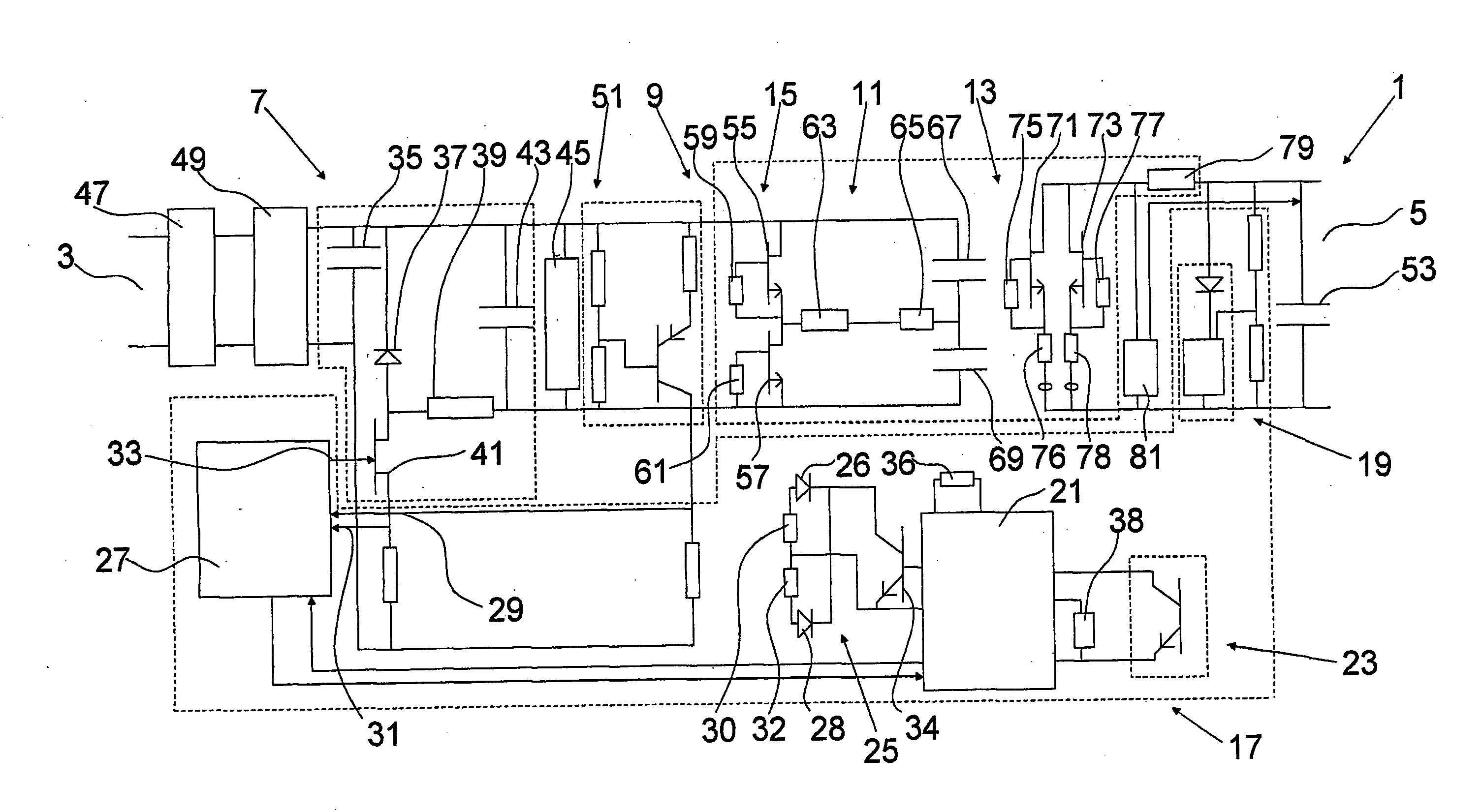
[0030]FIG. 1 is a diagrammatic view of an ACDC converter according to the present invention;

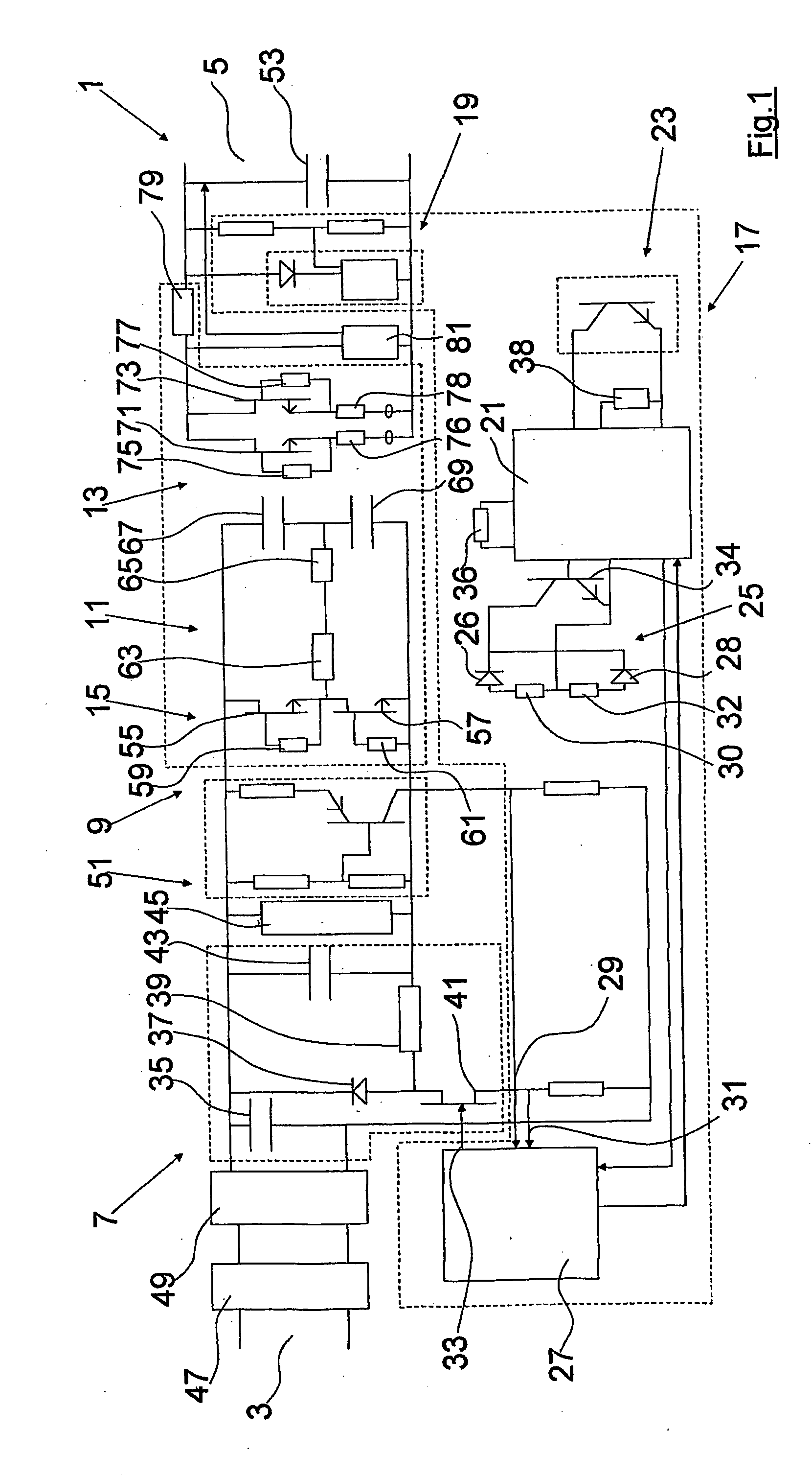
[0031]FIG. 2 is a diagrammatic view of an alternative transformer stage of the ACDC converter according to the present invention; and

[0032]FIG. 3 is a diagrammatic representation of a pulse set that may be used in accordance with the present invention.

[0033]Referring to the drawings and initially to FIG. 1 thereof there is shown an ACDC converter, indicated generally by the reference numeral 1, comprising a converter input 3 and a converter output 5, a pre-regulation stage 7, a DC transformer stage 9 comprising a transformer input stage 11 and a transformer output stage 13, and a controller 17. The transformer input stage 11 further comprises a double-ended converter input stage 15, and the control...


PUM


Abstract

This invention relates to an ACDC converter (1) comprising a converter input (3) and a converter output (5), a pre-regulation stage (7) and a DC transformer stage (9) comprising a transformer input stage (11) and a transformer output stage (13). The transformer input stage comprises a double ended converter and there is further provided a controller (17) for providing a control signal to the double ended converter. The controller (17) operates the ACDC converter using burst mode control and by sending control signals comprising pulse sets that are designed to provide substantially zero net magnetising current in the double ended converter. The pre-regulation stage preferably comprises a buck converter which in turn also provides power factor correction to the input of the ACDC converter.

Description

[0001]This invention relates to an ACDC converter comprising a converter input and a converter output, a pre-regulation stage, a DC transformer stage comprising a transformer input stage and a transformer output stage, the transformer input stage further comprising a double-ended converter input stage, and a controller for providing a control signal to the double-ended converter input stage.[0002]Over the last number of years, there have been many changes in the field of ACDC power converters. Many of these changes have been as a direct result of more stringent regulatory requirements imposed by governmental bodies. For the most part, there has been a drive towards providing more efficient ACDC converters and in particular, ACDC converters having a lower standby or no-load power loss. In order to meet these regulatory requirements, it has been found necessary to have stand-by or no-load losses as low as possible in power converters as it can have significant implications concerning ...

Claims


Application Information

Patent Timeline
Patent Type & Authority Applications(United States)
IPC IPC(8): H02M7/04
CPCH02M3/3376Y02B70/16H02M2007/4803H02M2001/0032Y02B70/10H02M1/0032H02M7/4803
Inventor YOUNG, GEORGETOMLINS, GARRYKEOGH, ANDREW BERNARD
Owner TEXAS INSTR INC
Why Eureka
Try Eureka