System, method and apparatus for image processing and image format

a technology of image processing and image format, applied in the field of image processing methods and equipment, can solve the problems of inability to use sensors or systems, inability to maintain minimum required level, and inability to achieve the minimum required level of information collection,

Active Publication Date: 2009-11-12
PANASONIC CORP
View PDF3 Cites 63 Cited by
  • Summary
  • Abstract
  • Description
  • Claims
  • Application Information

AI Technical Summary

Benefits of technology

[0049]According to the present invention, information about the shape of a given object in a normal environment or scene can be obtained based on the polarization information about the object.

Problems solved by technology

However, if the size of an optical system or an image capture device were reduced significantly, then the basic performance of the imaging device would decline too much to maintain the minimum required level in terms of sensitivity or diffraction limit of lens.
Nevertheless, for that purpose, the amount of information to collect is far too much to handle with conventional two-dimensional image processing.
However, such a sensor or system is not just bulky but also allows a distance of at most several meters between the camera and the object.
Besides, such a sensor or system cannot be used unless the object is a solid and bright diffusive object.
Under such a restriction, the sensor or system cannot be used to shoot an obj

Method used


Image

  • System, method and apparatus for image processing and image format
  • System, method and apparatus for image processing and image format
  • System, method and apparatus for image processing and image format

Examples


embodiment 1

[0095]First of all, a first preferred embodiment of an image input apparatus according to the present invention will be described.

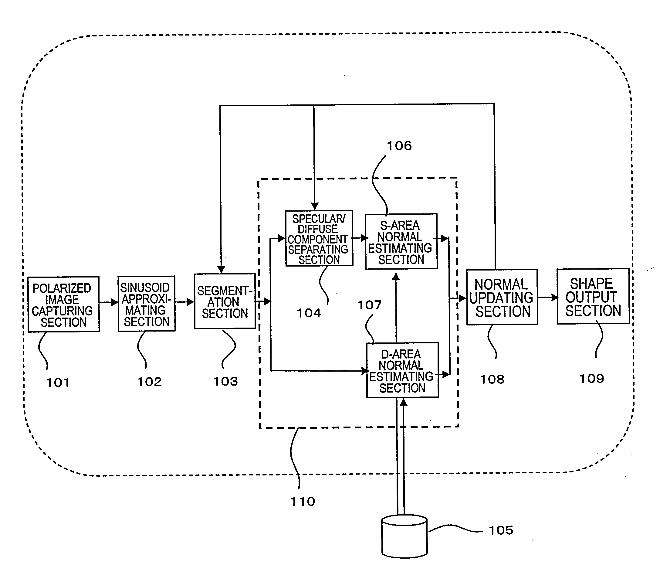
[0096]FIG. 1 is a block diagram showing a configuration for an image input apparatus as a first preferred embodiment of the present invention. This image input apparatus includes a polarized image capturing section 101, a sinusoid approximating section 102, a segmentation section 103, a normal estimating section 110, a normal updating section 108, and a shape output section 109. The normal estimating section 110 includes a specular / diffuse component separating section 104, an S-area normal estimating section 106 and a D-area normal estimating section 107. This image input apparatus gets refractive index information from the object's refractive index information database 105, which does not have to form an integral part of this image input apparatus.

[0097]The polarized image capturing section 101 is a device for taking a number of polarized images of the o...

embodiment 2

[0161]Hereinafter, a second preferred embodiment of an image input apparatus according to the present invention will be described.

[0162]First, look at FIG. 18, which is a block diagram illustrating an image input apparatus as a second preferred embodiment of the present invention.

[0163]The image input apparatus of this preferred embodiment is different from the counterpart of the first preferred embodiment described above in that this apparatus further includes a light source output section 1501 and a specular / diffuse reflected image output section 1502. Besides, the continuity evaluating section 1503 also operates differently. However, the other components are basically the same as the ones already described.

[0164]According to this preferred embodiment, not just the shape information of the object but also the angle of the light source that illuminates the object can be obtained. In addition, an image in which the light intensity component of the object has been separated into a sp...

embodiment 3

[0183]FIG. 23 is a block diagram illustrating a third preferred embodiment of an image input apparatus according to the present invention.

[0184]An image input apparatus as the third preferred embodiment of the present invention can process color images. The apparatus of this preferred embodiment can also output information about the object's shape, the angle of the light source that illuminates the object, and a specular reflected image and a diffuse reflected image of the object just like the counterpart of the second preferred embodiment described above.

[0185]The apparatus of this preferred embodiment includes a color polarized image capturing section 2001, a segmentation and adjusting section 2002, a Red processing section 2003, a Green processing section 2004, a Blue processing section 2005, a Red specular / diffuse reflected image output section 2006, a Green specular / diffuse reflected image output section 2007, a Blue specular / diffuse reflected image output section 2008, a norma...


PUM


Abstract

According to the present invention, a polarized image is captured, a variation in its light intensity is approximated with a sinusoidal function, and then the object is spatially divided into a specular reflection area (S-area) and a diffuse reflection area (D-area) in Step S402 of dividing a reflection area. Information about the object's refractive index is entered in Step S405, thereby obtaining surface normals by mutually different techniques in Steps S406 and S407, respectively. Finally, in Steps S410 and S411, the two normals are matched to each other in the vicinity of the boundary between the S- and D-areas.

Description

TECHNICAL FIELD[0001]The present invention relates to an image processing method and apparatus for reconstructing the surface shape of an object based on a polarized image thereof, and more particularly relates to an image processing technique that can collect information about the shape of the object or about a light source used in a shooting scene.BACKGROUND ART[0002]It is expected that cellphones with a camera, digital cameras, digital movie cameras and other imaging devices would achieve as high definition as an HDTV in the near future. Meanwhile, people are trying to reduce the sizes of those devices as much as possible in order to further increase their additional values. However, if the size of an optical system or an image capture device were reduced significantly, then the basic performance of the imaging device would decline too much to maintain the minimum required level in terms of sensitivity or diffraction limit of lens. For that reason, such a high-resolution trend sh...

Claims


Application Information

Patent Timeline
IPC IPC(8): G06K9/40G06T1/00
CPCG06T7/0055G02B5/3025G06T7/514
Inventor KANAMORL, KATSUHIROSATO, SATOSHI
Owner PANASONIC CORP
Why Eureka
Try Eureka