Single-Mode Optical Fiber Having Reduced Bending Losses

a single-mode optical fiber and bending loss technology, applied in the field of optical fiber transmission, can solve the problems of incompatible fiber commercially with some transmission systems, bending losses that are small in actual, and high cost of implementation, and achieve the effect of improving bending losses and sufficient attenuation of lp11 mod

Active Publication Date: 2009-11-12
DRAKA COMTEQ BV
View PDF99 Cites 204 Cited by
  • Summary
  • Abstract
  • Description
  • Claims
  • Application Information

AI Technical Summary

Benefits of technology

[0020]Accordingly, the present invention includes a fiber with a central core, an intermediate cladding, a depressed trench, and an external optical cladding. The refractive index profile improves the bending losses by a factor of ten relative to the constraints imposed by the G.657B standard, while retaining a mode field diameter compatible with the G.652 standard and ensuring a sufficient attenuation of the LP11 mode.

Problems solved by technology

Fiber manufacturing constraints may lead to a slightly different profile in the actual fiber.
Reducing the mode field diameter and / or increasing the effective cut-off wavelength reduces the MAC value but may lead to noncompliance with the G.652 standard, making the fiber commercially incompatible with some transmission systems.
The reduction of the bending losses, while retaining certain optical transmission parameters, constitutes a challenge for Fiber-To-The-Home (FTTH) applications.
Hole-assisted fiber technology makes it possible to achieve excellent performances with respect to bending losses, but this technology is complex and expensive to implement and cannot be used for fibers intended for low-cost FTTH systems.

Method used


Image

  • Single-Mode Optical Fiber Having Reduced Bending Losses
  • Single-Mode Optical Fiber Having Reduced Bending Losses
  • Single-Mode Optical Fiber Having Reduced Bending Losses

Examples


Embodiment Construction

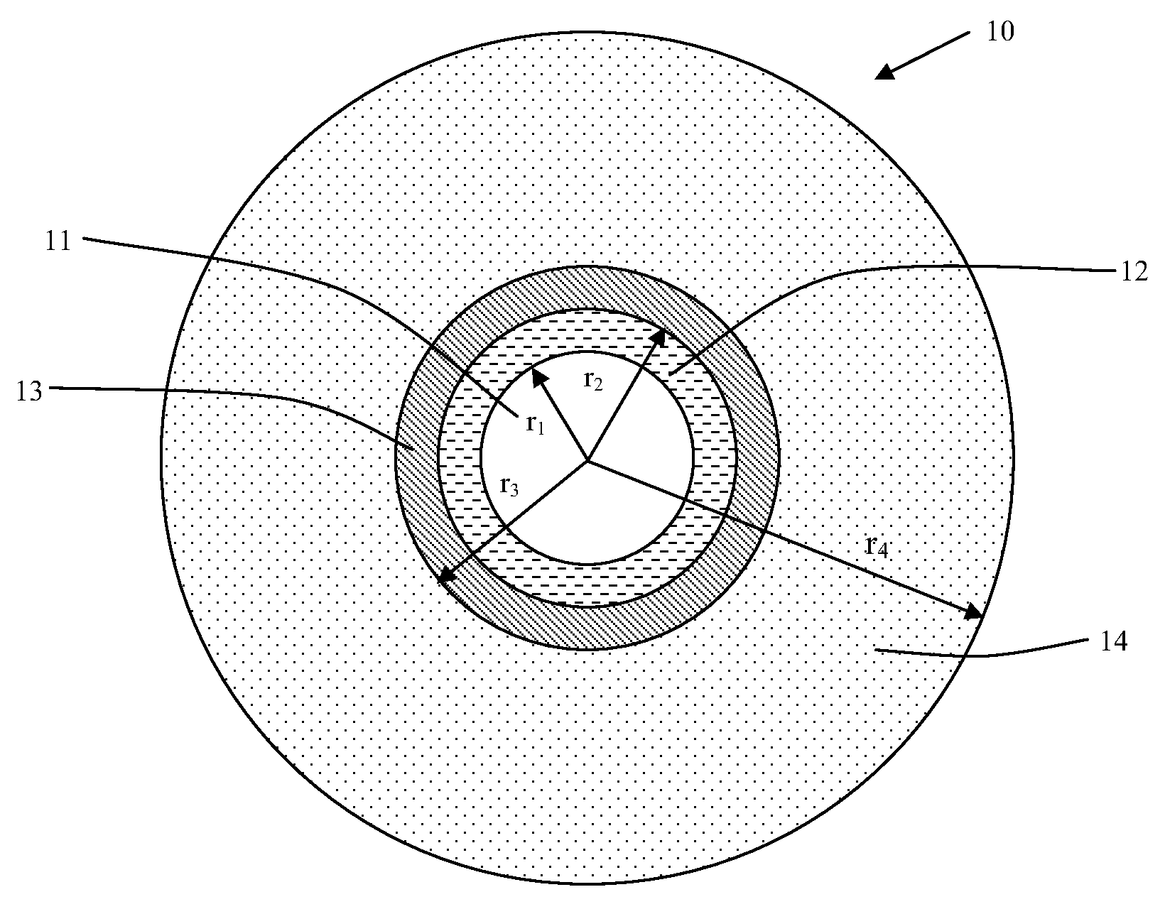
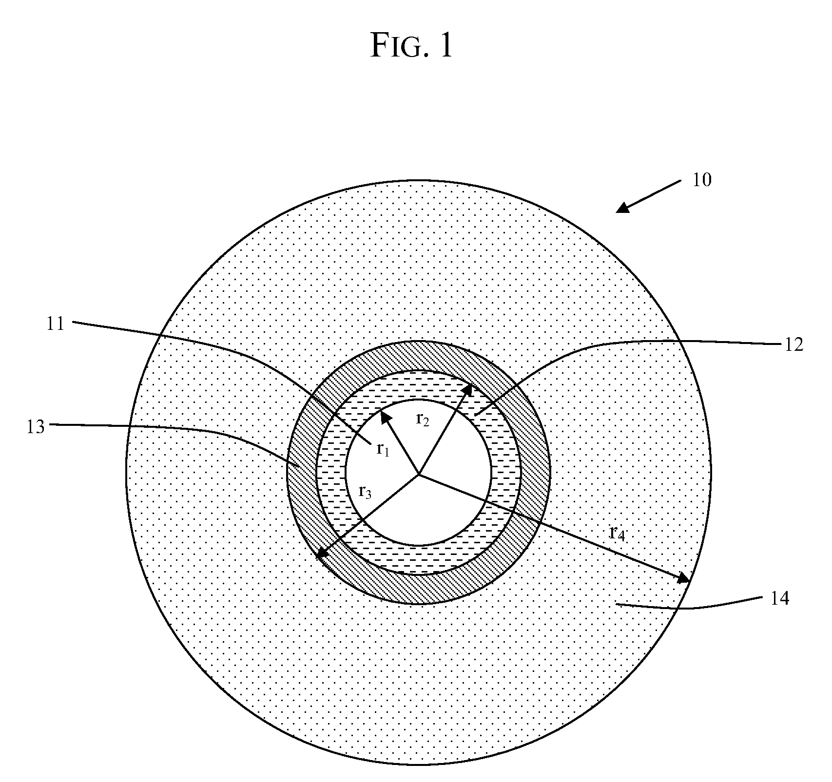
[0037]As depicted in FIG. 1, the optical fiber (10) of the invention has a central core (11), an intermediate cladding (12), and a depressed cladding (13). For purposes herein and without limiting the scope of the invention, depressed cladding means a radial portion of the fiber (10) having a refractive index less than the refractive index of the external optical cladding (14). Typically, the central core (11), the intermediate cladding (12), and the depressed cladding (13) are obtained by chemical vapor deposition in a silica tube. The external optical cladding (14) includes the silica tube and the overcladding on the tube. In typical embodiments, the overcladding is generally natural or doped silica, but can also be obtained by any other deposition technique (e.g., vapor axial deposition (“VAD”) or outside vapor deposition (“OVD”)).

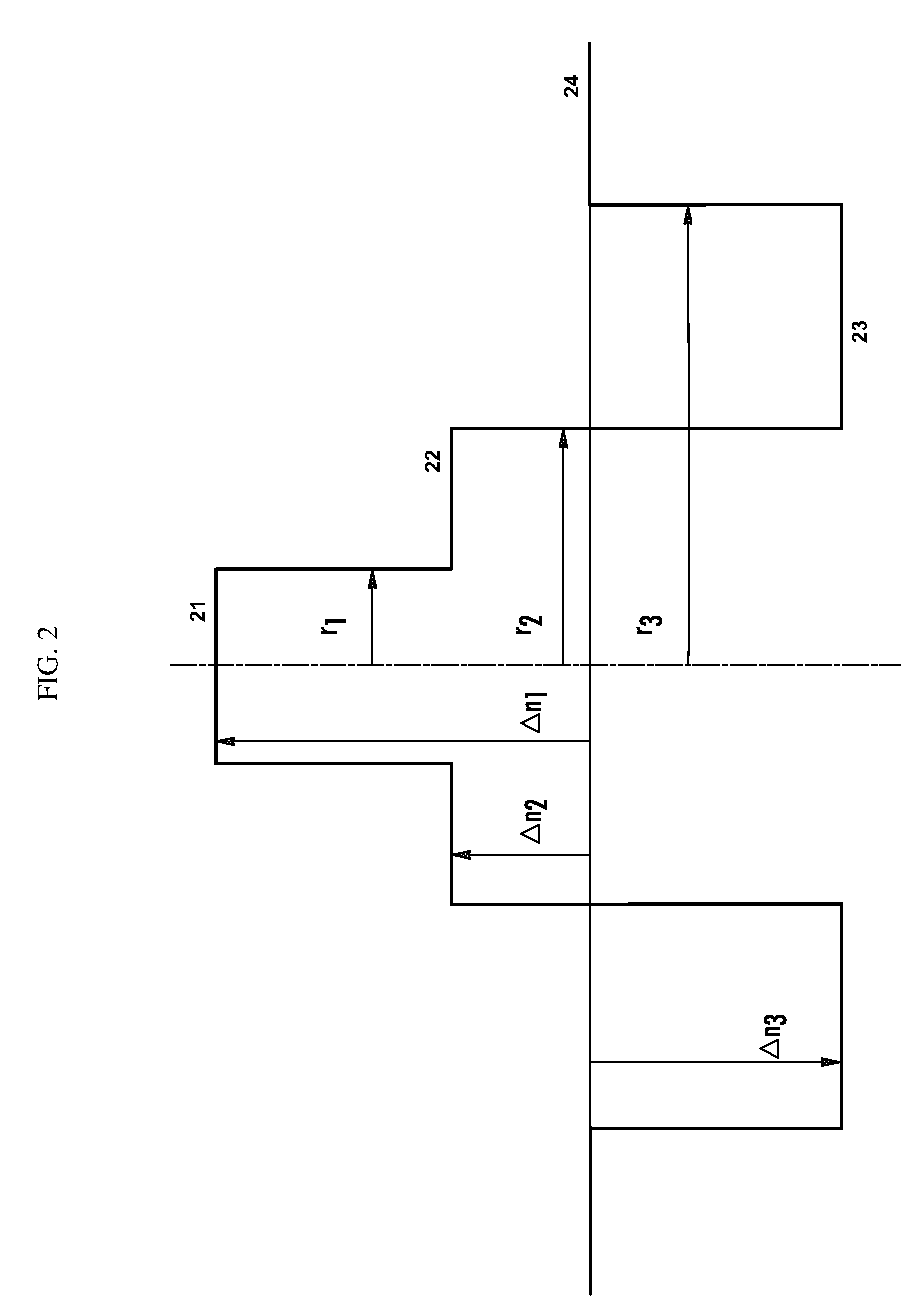
[0038]FIG. 2 illustrates a refractive index profile for the optical fiber (10) of FIG. 1. The profile of FIG. 2 is a set profile (i.e., representative ...


PUM


Abstract

A single-mode optical fiber includes a central core, an intermediate cladding, a depressed trench, and an external optical cladding. The central core has a radius r1 and a positive refractive index difference Δn1 with the optical cladding. The intermediate cladding has a radius r2 and a positive refractive index difference Δn2 with the optical cladding, wherein Δn2 is less than Δn1. The depressed trench has a radius r3 and a negative index difference Δn3 with the optical cladding. At a wavelength of 1310 nanometers, the optical fiber has a mode field diameter (MFD) between 8.6 microns and 9.5 microns and, at a wavelength of 1550 nanometers, the optical fiber has bending losses less than about 0.25×10⁻³ dB/turn for a radius of curvature of 15 millimeters. At a wavelength of 1260 nanometers, attenuation of the LP11 mode to 19.3 dB is achieved over less than 90 meters of fiber.

Description

CROSS-REFERENCE TO PRIORITY APPLICATIONS[0001]This application claims the benefit of pending French Application Ser. No. 08 / 02503 for “Fibre Optique Monomode” (filed May 6, 2008, at the French Patent Office), which is hereby incorporated by reference in its entirety.[0002]This application further claims the benefit of U.S. Patent Application No. 61 / 101,337 for a “Bend-Insensitive Optical Fiber” (filed Sep. 30, 2008), U.S. Patent Application No. 61 / 112,006 for a “Bend-Insensitive Single-Mode Optical Fiber” (filed Nov. 6, 2008), and U.S. Patent Application No. 61 / 112,374 for a “Bend-Insensitive Single-Mode Optical Fiber” (filed Nov. 7, 2008), each of which is incorporated by reference in their entirety.FIELD OF THE INVENTION[0003]The present invention relates to the field of optical fiber transmissions, and more specifically, to an optical fiber having greatly reduced bending losses.BACKGROUND OF THE INVENTION[0004]For optical fibers, the refractive index profile is generally set fort...

Claims


Application Information

Patent Timeline
Patent Type & Authority Applications(United States)
IPC IPC(8): G02B6/036
CPCG02B6/02266G02B6/02395G02B6/0365G02B6/028G02B6/036
Inventor DE MONTMORILLON, LOUIS-ANNERICHARD, SIMONMOLIN, DENISBOIVIN, DAVIDBIGOT-ASTRUC, MARIANNESILLARD, PIERRE
Owner DRAKA COMTEQ BV
Why Eureka
Try Eureka