
Multilayer information recording medium and method for manufacturing the same

Active Publication Date: 2009-11-12
PANASONIC CORP
View PDF6 Cites 0 Cited by
  • Summary
  • Abstract
  • Description
  • Claims
  • Application Information

AI Technical Summary

Benefits of technology

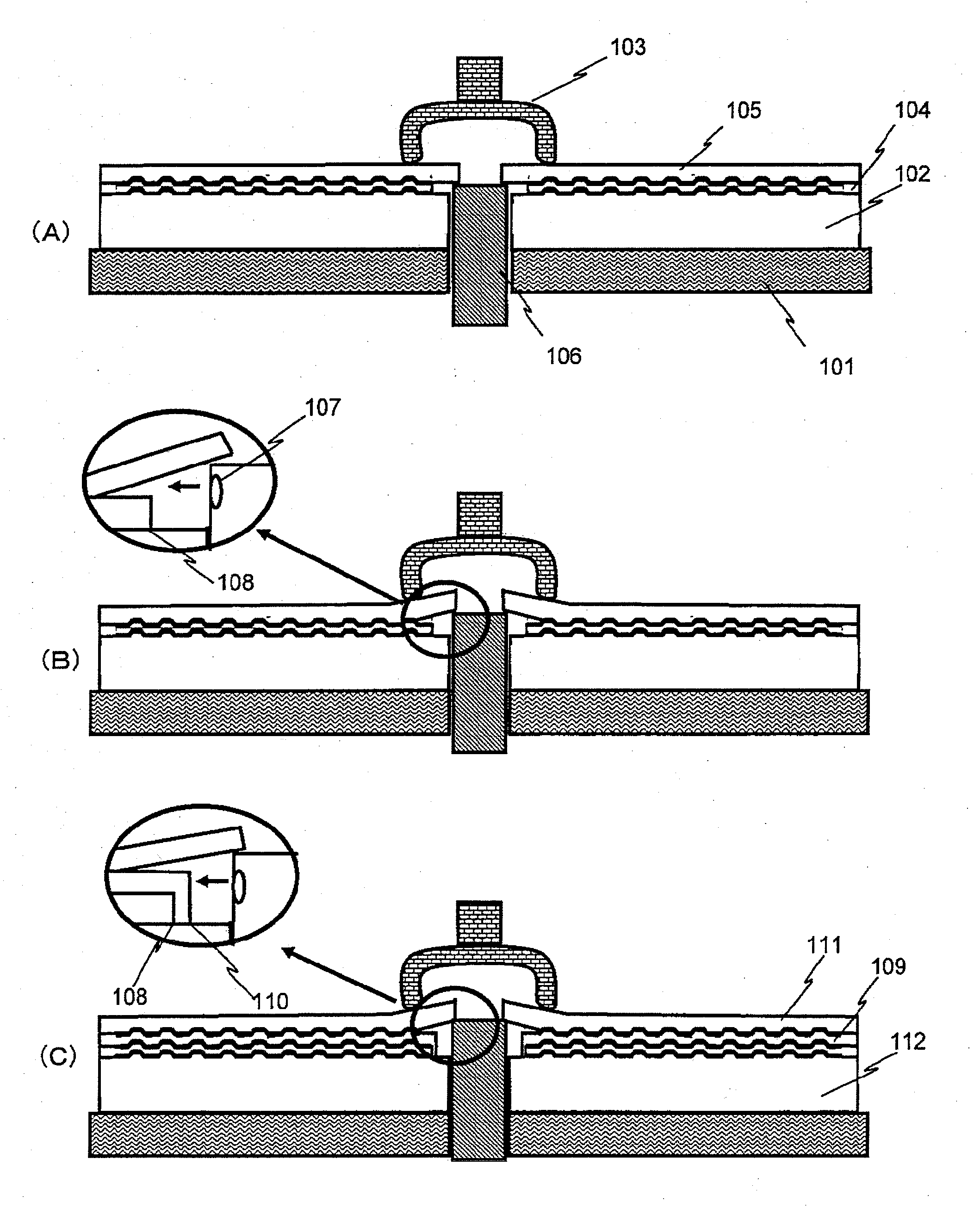
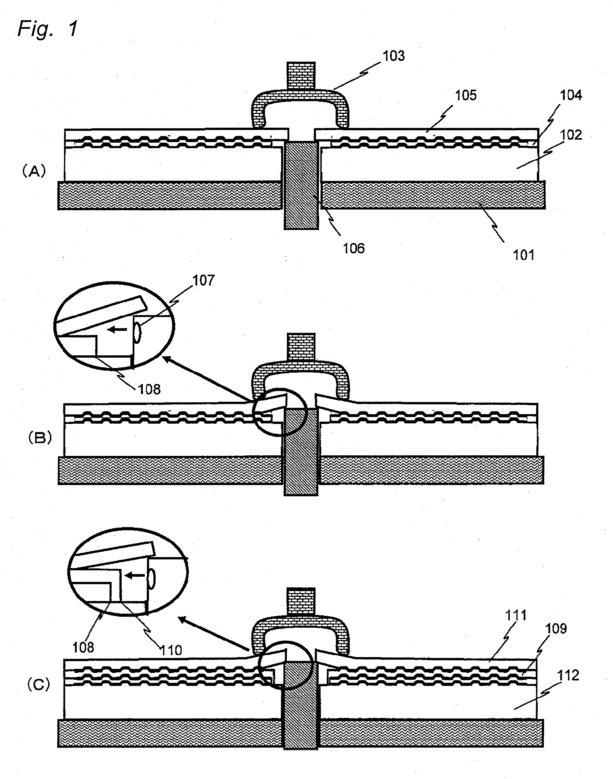
[0017]The multi-layer information recording medium of the present invention (may also be referred to simply as a “recording medium” or a “medium” hereinafter) is characterized in that the ends on the inner circumference side of the resin layers are not disposed at the same position along the radial direction of the substrate, and the end on the inner circumference side of at least one resin layer is covered by another resin layer(s). When peeling of the transfer substrate is carried out by starting at the inner circumference of the medium, the force applied to peel off the transfer substrate is concentrated at a point while the resin layers are formed repetitively, in case the ends on the inner circumference side of all the resin layers are located at the same position. In the recording medium of the present invention, the end on the inner circumference side of at least one resin layer is offset in order to avoid the concentration of force. In the recording medium of the present invention, in addition, the end on the inner circumference side of at least one resin layer (referred to as A for convenience) is covered by another resin layer (referred to as B for convenience) that is formed after forming the resin layer A, so as to decrease the force exerted on the resin layer A when the transfer substrate bonded on the resin layer B is peeled off.
[0021]According to the multi-layer information recording medium of the present invention and the method for manufacturing the same, it is made possible to reduce the number or the ratio of defects which are caused by the peeling of the transfer substrate bonded to the resin layer when the resin layer is formed as an intermediate layer. Thus the present invention enables it to stably manufacture the multi-layer information recording medium on or from which a large amount of information is recorded or reproduced satisfactorily.

Problems solved by technology

Since the adhesion of the resin layer onto the transfer substrate makes it impossible to properly separate the information recording layers, and therefore signals cannot be recorded on the two information recording layers that are disposed above and below the resin layer.
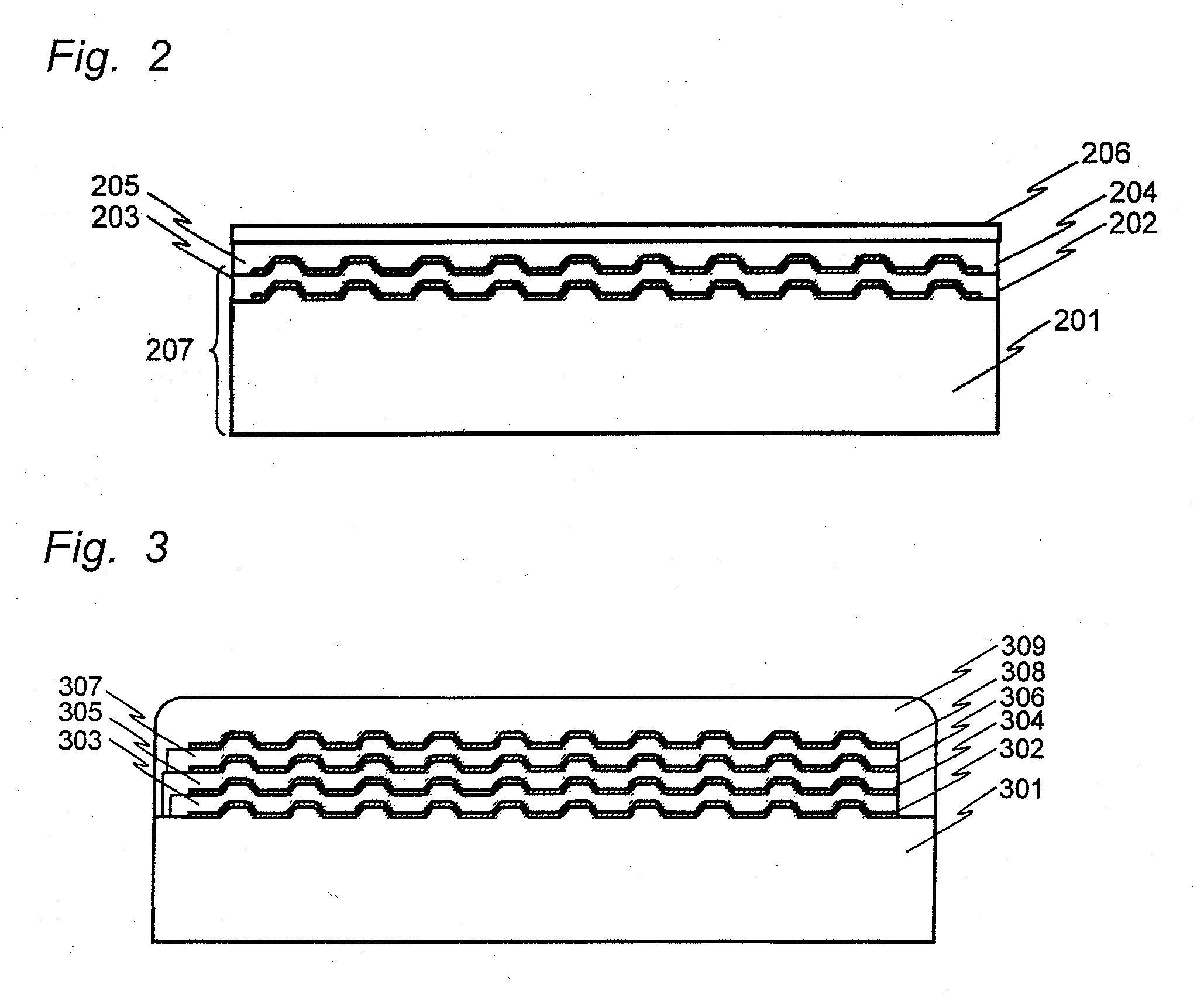
Such a problem described above tends to occur when the process of forming the resin layers of two-layer recording medium of the prior art shown in FIG. 2 is applied to the formation process of the resin layers of the multi-layer recording medium.
When manufacturing the multi-layer information recording medium, in particular, since the process of forming the resin layer is carried out twice or more, a larger number of the layers makes it difficult to manufacture good media, thus resulting in lower productivity.

Method used


Image

  • Multilayer information recording medium and method for manufacturing the same
  • Multilayer information recording medium and method for manufacturing the same
  • Multilayer information recording medium and method for manufacturing the same

Examples


first embodiment

[0082]FIG. 7(A) shows one embodiment of the four-layer information recording medium in sectional view. This drawing is a sectional view of the information recording medium constituted from a first information recording layer 702, a first resin layer 706, a second information recording layer 703, a second resin layer 707, a third information recording layer 704, a third resin layer 708, a fourth information recording layer 705 and a protective layer 709 that are stacked in this order on a substrate 701.

[0083]In this embodiment, positions of the ends on the inner circumference side of the resin layers are all made different and the ends on the inner circumference side of all the resin layers are in contact with the substrate 701. For example, when the inner diameter of the substrate 701 (diameter of the center hole) is 15 mm, three resin layers may be formed so that the inner diameter of the first resin layer 706 (equal to the diameter of a circle defined by the end on the inner circu...

second embodiment

[0094]FIG. 7(B) shows another embodiment of the four-layer information recording medium in sectional view. This drawing is a sectional view of the information recording medium constituted from a first information recording layer 714, a first resin layer 718, a second information recording layer 715, a second resin layer 719, a third information recording layer 716, a third resin layer 720, a fourth information recording layer 717 and a protective layer 721 stacked in this order on a substrate 713.

[0095]In this embodiment, too, positions of the ends on the inner circumference side of the resin layers are all made different in order to prevent defects from occurring during peel operation. Specifically, the end on the inner circumference side of the first resin layer 718 is located nearest to the inner circumference of the substrate 713, the end on the inner circumference side of the second resin layer 719 is located nearer to the outer circumference of the substrate than the end on th...

third embodiment

[0110]A method of dividing the resin layer into areas and differentiating the dose of ultraviolet ray irradiation among the areas when curing the resin layers will now be described as the third embodiment. In a multi-layer disk, transmittance greatly differs between the information recording region where recording layer is formed and the other region (referred to as “non-information recording region”). As a result, the resin layer in the non-information recording region is exposed to much ultraviolet ray every time the resin layer is formed.

[0111]The non-information recording region, as well as a method for manufacturing the information recording medium by changing the dose of ultraviolet ray irradiation, will be described with reference to FIG. 8. Resin layers 803, 805, 807 of ultraviolet curable resin and a transparent layer (or protective layer) 809 of ultraviolet curable resin are formed on a substrate 801, while a first information recording layer 802, a second information reco...


PUM


Abstract

A multi-layer information recording medium comprising a substrate that has an inner circumference and an outer circumference, three or more information recording layers and resin layers disposed between the information recording layers, wherein positions of the ends on the inner circumference side of the resin layers are different from each other in at least one combination of two neighboring resin layers, and the end on the inner circumference side of at least one of the resin layers is covered by another resin layer.

Description

TECHNICAL FIELD[0001]The present invention relates to an information recording medium used in reproduction or recording / reproduction of information and a method for manufacturing the same.BACKGROUND ART[0002]As increasing amount of information is required by information apparatuses, audio-visual apparatuses, and the like in recent years, information recording media such as optical disks have attracted attention for the advantages thereof such as the ease of access to data, large data storage capacity and possibility of reducing the size of apparatuses, and the recording density thereof has become increasingly higher. As the means for increasing the recording density of an optical disk, for example, such a recording and reproduction head has been put into use that uses laser beam having wavelength of about 400 nm and a condenser lens having numerical aperture (NA) of 0.85 for focusing the laser beam. Use of such a recording and reproduction head enables it to achieve a storage capaci...

Claims


Application Information

Patent Timeline
IPC IPC(8): B32B3/02B32B37/02G11B7/24G11B7/24035G11B7/24038G11B7/254G11B7/257
CPCG11B7/24038Y10T428/21G11B7/26G11B7/256G11B7/24073
Inventor TOMEKAWA, YUUKOTOMIYAMA, MORIO
Owner PANASONIC CORP
Learn More