Electrical contact element for contacting an electrical test sample and contacting apparatus

a technology of electrical contact elements and electrical test samples, applied in the direction of electrically conductive connections, coupling device connections, test/measuring connectors, etc., can solve the problems of unintentional touching of contact elements, short circuits, and inability to achieve conventional technology, etc., to achieve large current-carrying capacity and large cross-section

Active Publication Date: 2009-11-12
FEINMETALL
View PDF31 Cites 22 Cited by
  • Summary
  • Abstract
  • Description
  • Claims
  • Application Information

AI Technical Summary

Benefits of technology

[0004]It is therefore an object of the invention to provide an electrical contact element of the aforementioned type which, given a smaller but adequate contact force, provides a large cross-section and thus a large current-carrying capacity. It is a further object to provide an electrical contact element that is usable, in particular, with very small contact distances.

Problems solved by technology

Due to components under test becoming ever more compact and the associated decreasing electrical contact separations, increasingly, problems arise with the aforementioned known contact elements.
In other words, the small contact separations cannot be achieved with conventional technology, or they lead to contact elements unintentionally touching and creating short circuits.
The smaller cross-sections can result in burning through if the test currents are required to be at a particular level.

Method used


Image

  • Electrical contact element for contacting an electrical test sample and contacting apparatus
  • Electrical contact element for contacting an electrical test sample and contacting apparatus
  • Electrical contact element for contacting an electrical test sample and contacting apparatus

Examples


Embodiment Construction

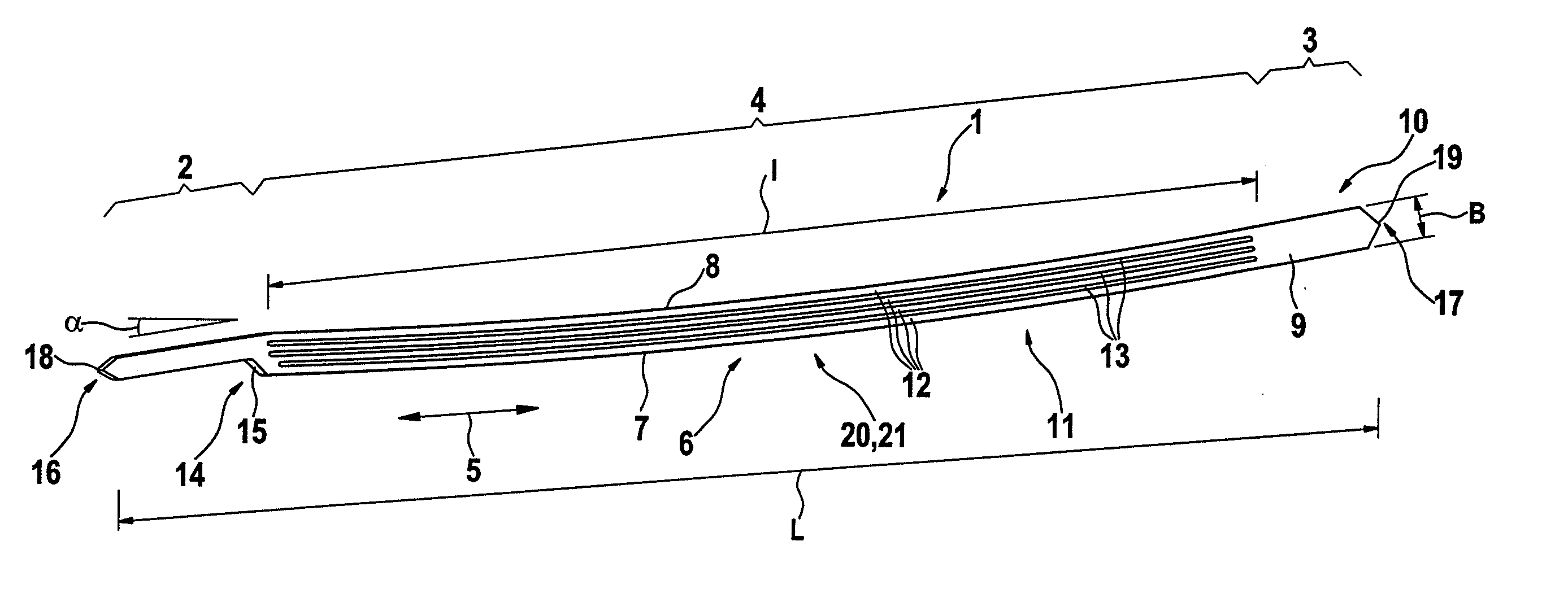
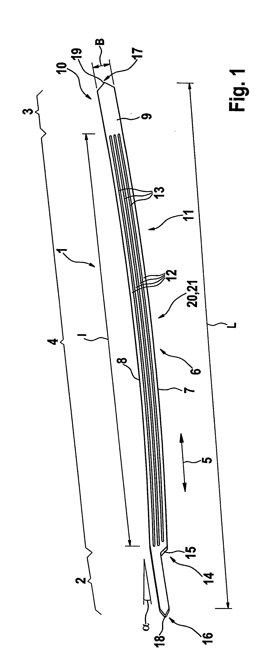
[0036]FIG. 1 shows an elongate electrical contact element 1, which serves to make contact with electrical components under test. The contact element 1 has two end regions 2 and 3 and an elongate intermediate region 4 lying therebetween. The two end regions 2 and 3 are also configured elongate. Therefore, overall the contact element has a longitudinal extent that is indicated with a double-headed arrow 5.

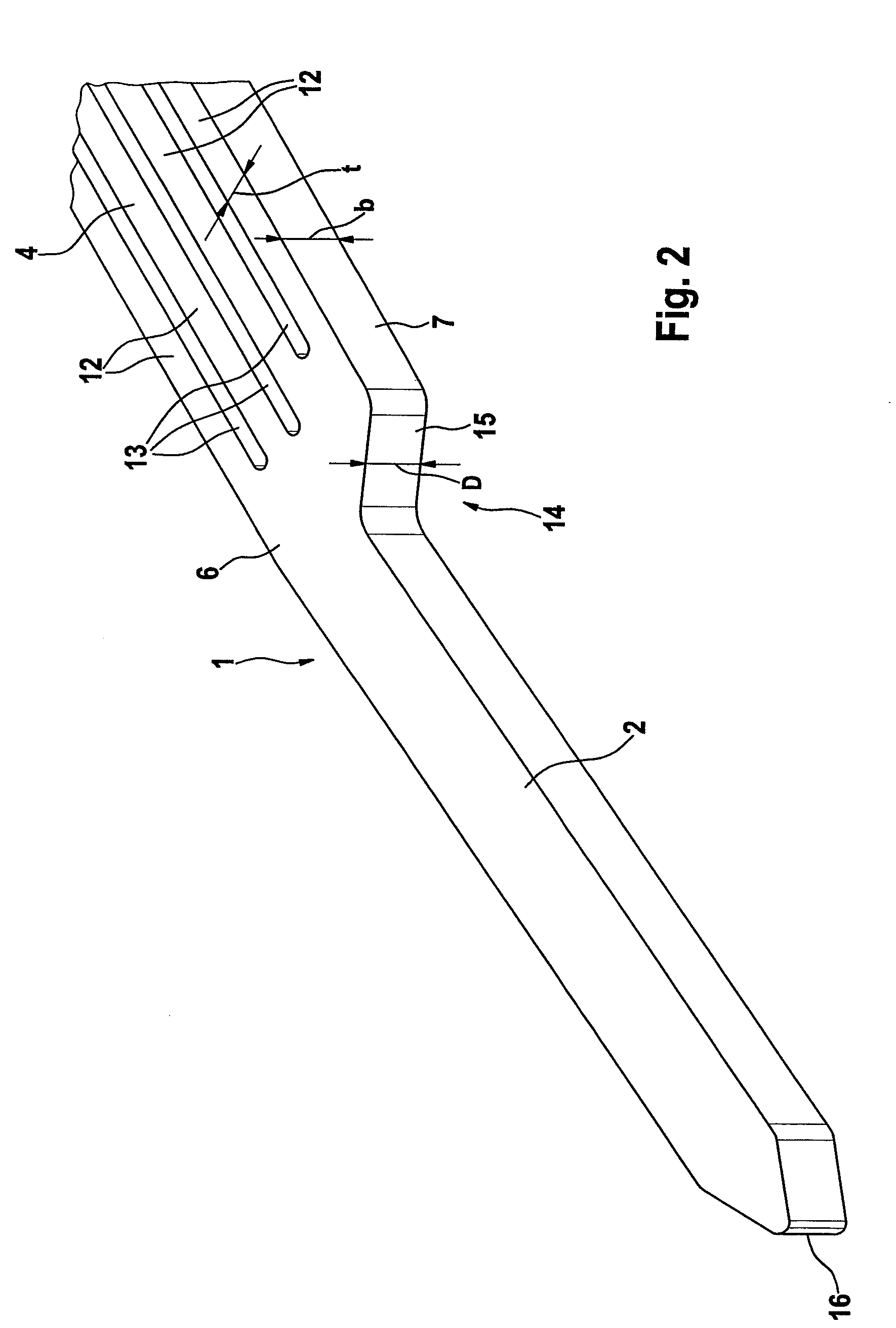
[0037]The contact element 1 is configured in one piece. It comprises a single-piece contact body 6. The contact element 1 has two longitudinal sides 7, 8, a front side 9 and a rear side 10 opposing the front side. It has a length L, a width B and a thickness D (FIG. 2). Due to its elongate form, the contact element 1 is essentially configured as a contact strip 11. This circumstance results, in particular, therefrom that the length L is configured greater than the width B and said width B is greater than the thickness D.

[0038]As shown in the drawings, the intermediate region 4 is con...


PUM


Abstract

An elongate electrical contact element (1) for physically contacting electrical components under test, having two electrical contacting end regions (2, 3) and an elongate intermediate region (4) situated between the end regions (2, 3). The intermediate region (4) has an essentially rectangular cross-section and is configured lamellar along its longitudinal extent. Also disclosed is a corresponding contacting apparatus (22) including such a contact element (1) and a contact element holder (23).

Description

[0001]The following disclosure is based on German Patent Application No. 10 2008 023 761.2, filed on May 9, 2008, which is incorporated into this application by reference.FIELD OF AND BACKGROUND OF THE INVENTION[0002]The invention relates to an elongate electrical contact element for physically contacting an electrical component under test, comprising two electrical contacting end regions and an elongate intermediate region situated between the end regions.[0003]Contact elements of this type are known in the form of spring contact probes or buckling beams. They are held by a contact element holder and serve to contact the electrical component under test with one end region and, with the other end region, to make contact with an electrical test apparatus, so that test current paths are created to the electrical component under test and the test apparatus can test the component under test for fault-free electrical function. The known contact elements configured as spring contact probe...

Claims


Application Information

Patent Timeline
Patent Type & Authority Applications(United States)
IPC IPC(8): H01R11/18H01R13/02
CPCG01R1/06733H01R2201/20G01R1/07357G01R1/0675H01R13/2407H01R13/2435G01R1/067G01R1/073
Inventor WEILAND, ACHIMBOEHM, GUNTHER
Owner FEINMETALL
Why Eureka
Try Eureka