Ocular Implantation Device

Active Publication Date: 2009-11-12
SILICON VALLEY BANK
View PDF7 Cites 113 Cited by
  • Summary
  • Abstract
  • Description
  • Claims
  • Application Information

AI Technical Summary

Benefits of technology

[0006]There are numerous drawbacks of such techniques for implant delivery. Extensive handling of the implant is necessitated in these techniques, creating a risk that the implant will be damaged in the process. Many implants are polymer-based and are relatively fragile. If portions of the implants are damaged and broken-off, the effective therapeutic dose delivered by the implant once placed will be significantly altered. In addition, it becomes inherently difficult using these methods to achieve reproducible placement from patient to patient. Additionally, all of these techniques require an incision or puncture in the eye large enough to require su

Problems solved by technology

A primary difficulty in treating diseases of the eye is the inability to introduce drugs or therapeutic agents into the eye and maintain these drugs or agents at a therapeutically effective concentration in the eye for the necessary duration.
Systemic administration may not be an ideal solution because, often, unacceptably high levels of systemic dosing are needed to achieve effective intraocular concentrations thus increasing the incidence of unacceptable side effects of the drugs.
Simple ocular instillation or application is not an acceptable alternative in many cases because the drug may be quickly washed out by tear-action or may otherwise be depleted from the eye into the general circulation.
Suprachoroidal injections of drug solutions have been performed, but again the drug availability is short-lived.
In summary, available methods make it difficult to maintain therapeutic le

Method used


Image

  • Ocular Implantation Device
  • Ocular Implantation Device
  • Ocular Implantation Device

Examples


Embodiment Construction

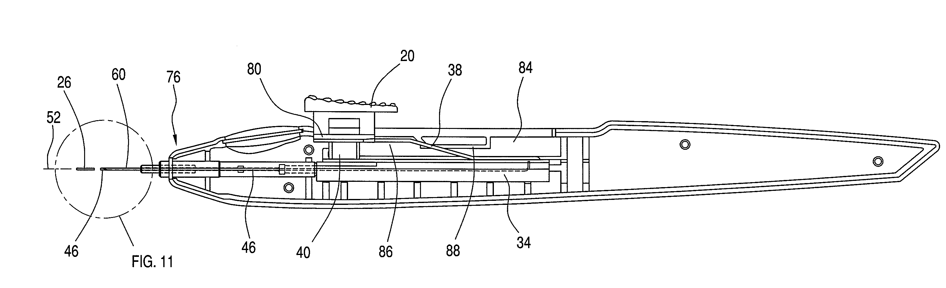
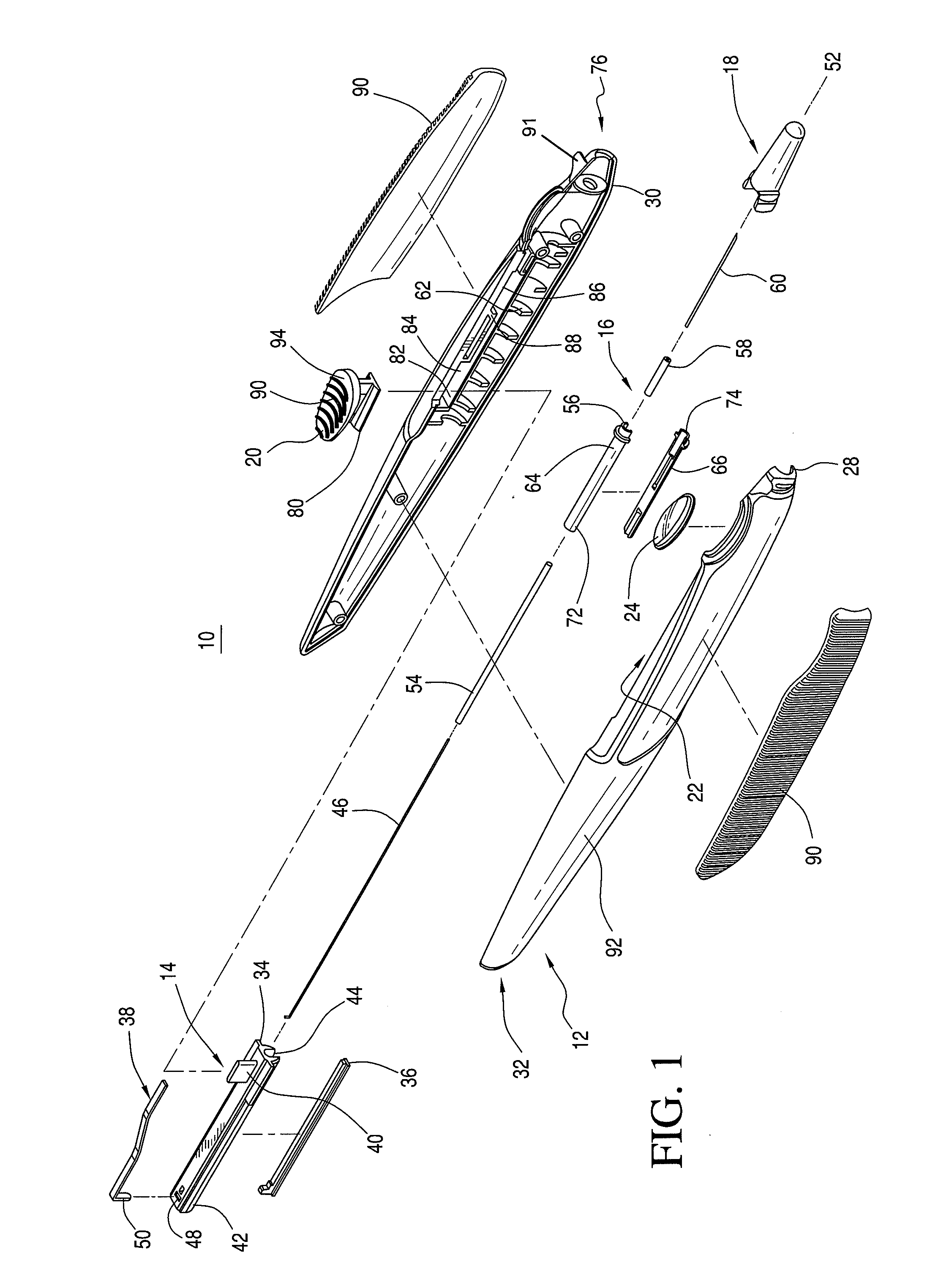
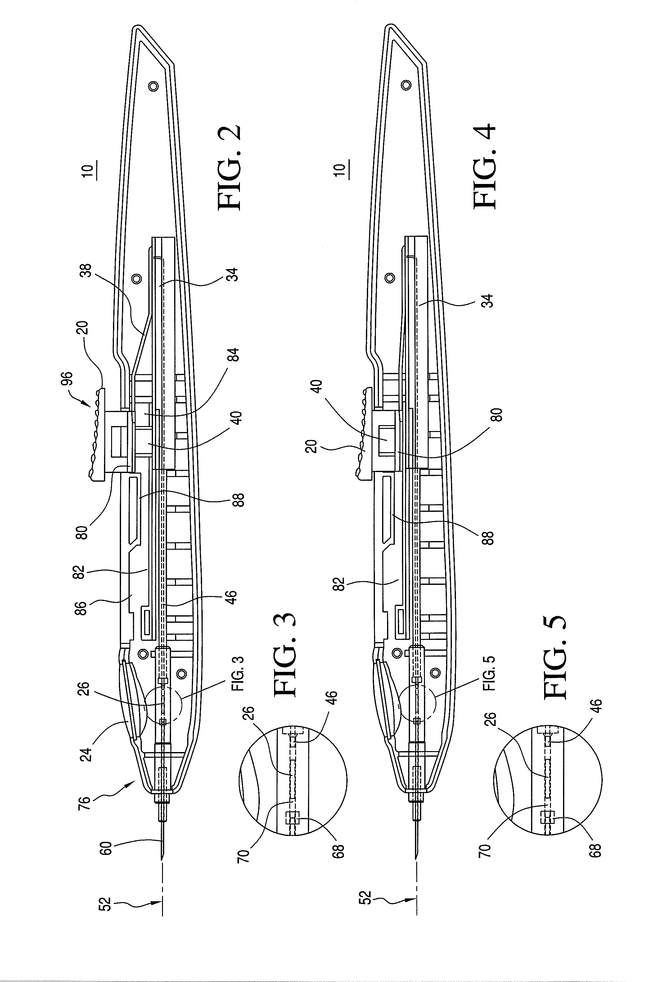
[0036]An ocular implantation device is disclosed that provides a user a visual indication of the status of an implant to be delivered to a target tissue prior to delivery. The device further provides a tactile indication of the status of the implant to be delivered prior to delivery.

[0037]As used herein, the term “implants” refers to ocular implants or drug delivery devices that can be implanted into any number of locations in the eye and that may release a controlled amount of a bioactive agent or therapeutic immediately or over time. The term implants may include microimplants that have a sufficiently small cross-sectional area that they can be delivered by methods and / or using devices according to the invention that result in self-sealing of the eye at the puncture site associated with the delivery.

[0038]Although many implantable devices may be suitable for use with the ocular implantation device disclosed herein, devices having a tube shape, such as those described in U.S. Pat. ...


PUM


Abstract

An ocular implantation device comprises a housing having a longitudinal axis, a needle configured to receive an implant, and a plunger and a rod operatively coupled together. The plunger and the rod are disposed in the housing and are collectively, translationally moveable along the longitudinal axis of housing. The rod is configured to be receivable within at least a portion of the needle to enable the rod to move an implant therethrough. An actuator is operatively engaged with the plunger such that movement of the actuator in a direction aligned with the longitudinal axis of the housing results in translational movement of the plunger and the rod along the longitudinal axis of the housing in order to deliver the implant through the needle to a target site. An alternative embodiment of the device uses a retractable needle to deliver the implant.

Description

RELATED APPLICATIONS[0001]The present patent document claims the benefit of the filing date under 35 U.S.C. §119(e) of Provisional U.S. patent application Ser. Nos. 60 / 986,464, filed Nov. 8, 2007, and 61 / 075,786, filed Jun. 26, 2008, which are hereby incorporated by reference in their entirety.FIELD[0002]The invention relates to a device for delivering ocular implants into the vitreous of the eye. Specifically, the invention relates to an ergonomically shaped injector containing a needle capable of puncturing the eye and delivering an implant into the vitreous of the eye.BACKGROUND[0003]A primary difficulty in treating diseases of the eye is the inability to introduce drugs or therapeutic agents into the eye and maintain these drugs or agents at a therapeutically effective concentration in the eye for the necessary duration. Systemic administration may not be an ideal solution because, often, unacceptably high levels of systemic dosing are needed to achieve effective intraocular con...

Claims


Application Information

Patent Timeline
IPC IPC(8): A61F9/007
CPCA61F9/0017A61M5/322A61K9/0051A61M37/0069A61M2210/0612
Inventor HIGHLEY, BRIANBEESON, MORGANJACKSON, RANDYWAYMAN, CHRISTOPHER EDWARDSHETLER, LANCECUTINO, ANTONIOWRIGHT, MICHAEL THOMAS
Owner SILICON VALLEY BANK
Why Eureka
Try Eureka