Concrete agitating drum driving device

a technology of agitating drums and driving devices, which is applied in the direction of road transportation, fluid couplings, servomotors, etc., can solve the problems difficulty in maintaining the discharge flow rate of hydraulic pumps, etc., and achieves the effect of increasing reducing the fuel consumption amount of internal combustion engines

Inactive Publication Date: 2009-11-19
KYB CORP
View PDF4 Cites 16 Cited by
  • Summary
  • Abstract
  • Description
  • Claims
  • Application Information

AI Technical Summary

Benefits of technology

[0007]In order to maintain the pump discharge flow rate of the hydraulic pump at a constant flow rate, it may be necessary to regulate an output torque of the internal combustion engine. For example, within a range from the idle rotation speed region to a low rotation speed region, it may be necessary to increase a fuel supply amount to the internal combustion engine to input a sufficient rotating torque into the hydraulic pump in which the discharge amount of pressurized working oil per unit rotation has been increased. However, engine control of this kind increases the fuel consumption amount of the internal combustion engine.
[0008]It is therefore an object of this invention to reduce a fuel consumption amount of an internal combustion engine which is used as a power source for driving a concrete agitating drum for ready-mixed concrete.
[0009]In order to achieve the above object, this invention provides a concrete agitating drum driving device comprising a hydraulic motor mechanical

Problems solved by technology

However, it is difficult to maintain the discharge flow rate of the hydraulic pump at a constant flow rate throughout the engine rotation speed range from an idle rotation speed region to a high rot

Method used


Image

  • Concrete agitating drum driving device
  • Concrete agitating drum driving device
  • Concrete agitating drum driving device

Examples


Embodiment Construction

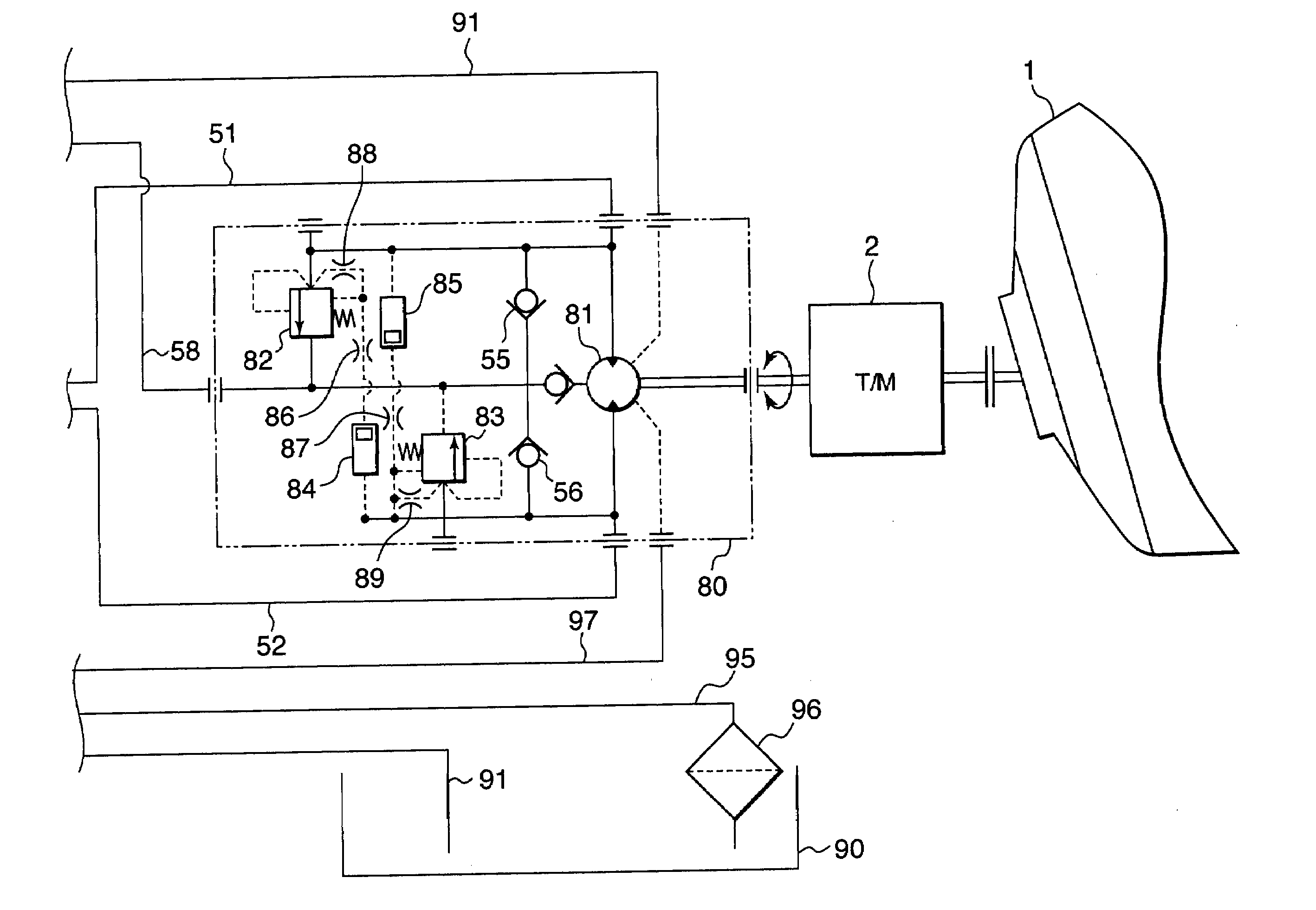
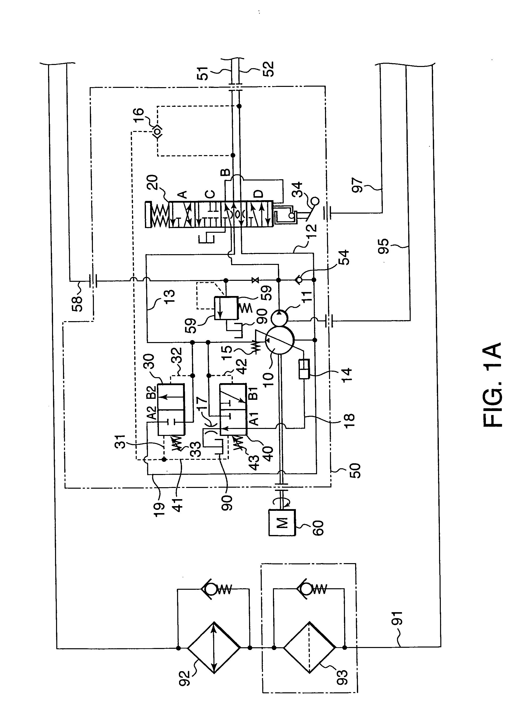
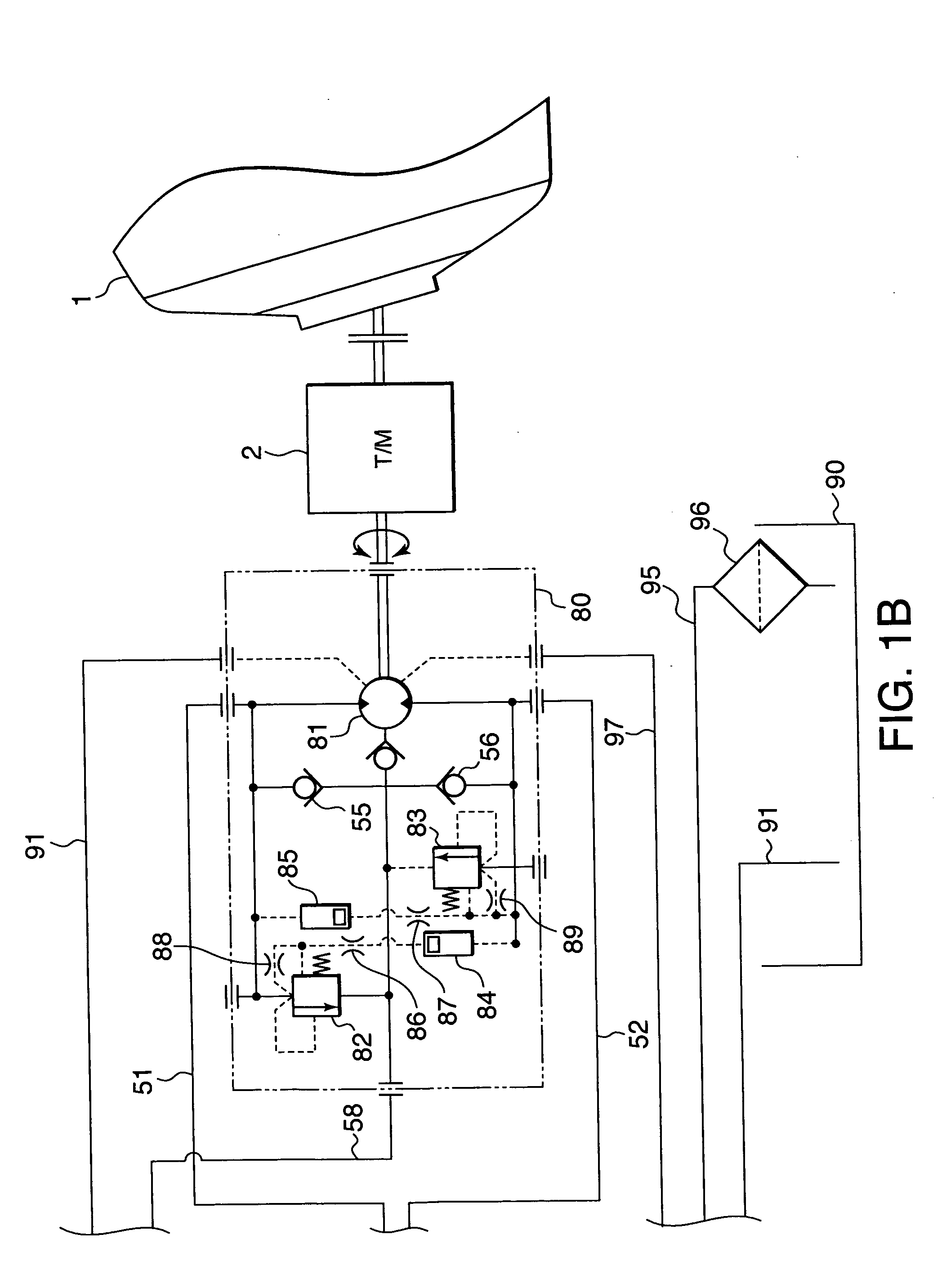
[0021]Referring to FIGS. 1A and 1B of the drawings, a concrete agitating drum driving device for a ready-mixed concrete agitating truck comprises a pump unit 50, a motor unit 80, a reservoir 90, and hydraulic passages connecting these units and the reservoir.

[0022]The motor unit 80 comprises a hydraulic motor 81 which rotates a concrete agitating drum 1 via a transmission 2.

[0023]The hydraulic motor 81 comprises two ports to which a first hydraulic passage 51 and a second hydraulic passage 52 are connected respectively. The hydraulic motor 81 rotates in a normal direction and a reverse direction according to a hydraulic pressure supplied selectively to the first hydraulic passage 51 and the second hydraulic passage 52.

[0024]A relief valve 82 is connected to the first hydraulic passage 51. A pressure in the first hydraulic passage 51 is input into the relief valve 82 as a pilot pressure to open the relief valve 82. A pressure in the second hydraulic passage 52 is input into the relie...


PUM

PropertyMeasurementUnit
Forceaaaaaaaaaa
Pressureaaaaaaaaaa
Speedaaaaaaaaaa

Abstract

A concrete agitating drum (1) is driven by a hydraulic motor (81). A connection switch-over valve (20) is arranged to have a function to regulate a flow cross-sectional area of pressurized working oil supplied to the hydraulic motor (81) from a variable capacity hydraulic pump (10). The variable capacity hydraulic pump (10) is driven by a combustion engine (60) together with a charge pump (11). When a discharge pressure of the charge pump (11) is low, the connection switch-over valve (20) maintains a small flow cross-sectional area to rotate the agitating drum (1) at a low rotation speed so that fuel consumption of the combustion engine (60) is suppressed to be small. When the discharge pressure of the charge pump (11) becomes high, the connection switch-over valve (20) enlarges the flow cross-sectional area, thereby realizing a rated rotation speed of the agitating drum (1).

Description

FIELD OF THE INVENTION[0001]This invention relates to an agitating drum driving device for a concrete agitating truck using a variable capacity hydraulic pump and a hydraulic motor.BACKGROUND OF THE INVENTION[0002]A ready-mixed concrete agitating truck is equipped with a concrete agitating drum for agitating and discharging ready-mixed concrete supplied from a hopper or the like. The agitating drum is driven by a hydraulic motor.[0003]JP2000-272405A, published by the Japan Patent Office in 2000, proposes a hydraulic drive circuit for such a concrete agitating drum.[0004]In this hydraulic drive circuit, the hydraulic motor is supplied with pressurized oil from a variable capacity hydraulic pump via a connection switch-over valve. The connection switch-over valve has a function to select a direction in which the pressurized oil discharged from the variable capacity hydraulic pump is supplied to the hydraulic motor as well as to shut off supply of the pressurized oil to the hydraulic m...

Claims


Application Information

Patent Timeline
IPC IPC(8): F15B11/02
CPCB28C5/4213B28C5/422F15B7/005F15B7/008F15B2211/20553F15B2211/20584Y02T10/76F15B2211/615F15B2211/62F15B2211/7058F16H61/4061F16H61/47F15B2211/50527B28C5/42B60P3/16F15B11/00
Inventor ANDO, KUNIHIROABE, MASAYAIWASAKI, YOSHIHITO
Owner KYB CORP
Why Eureka
Try Eureka