

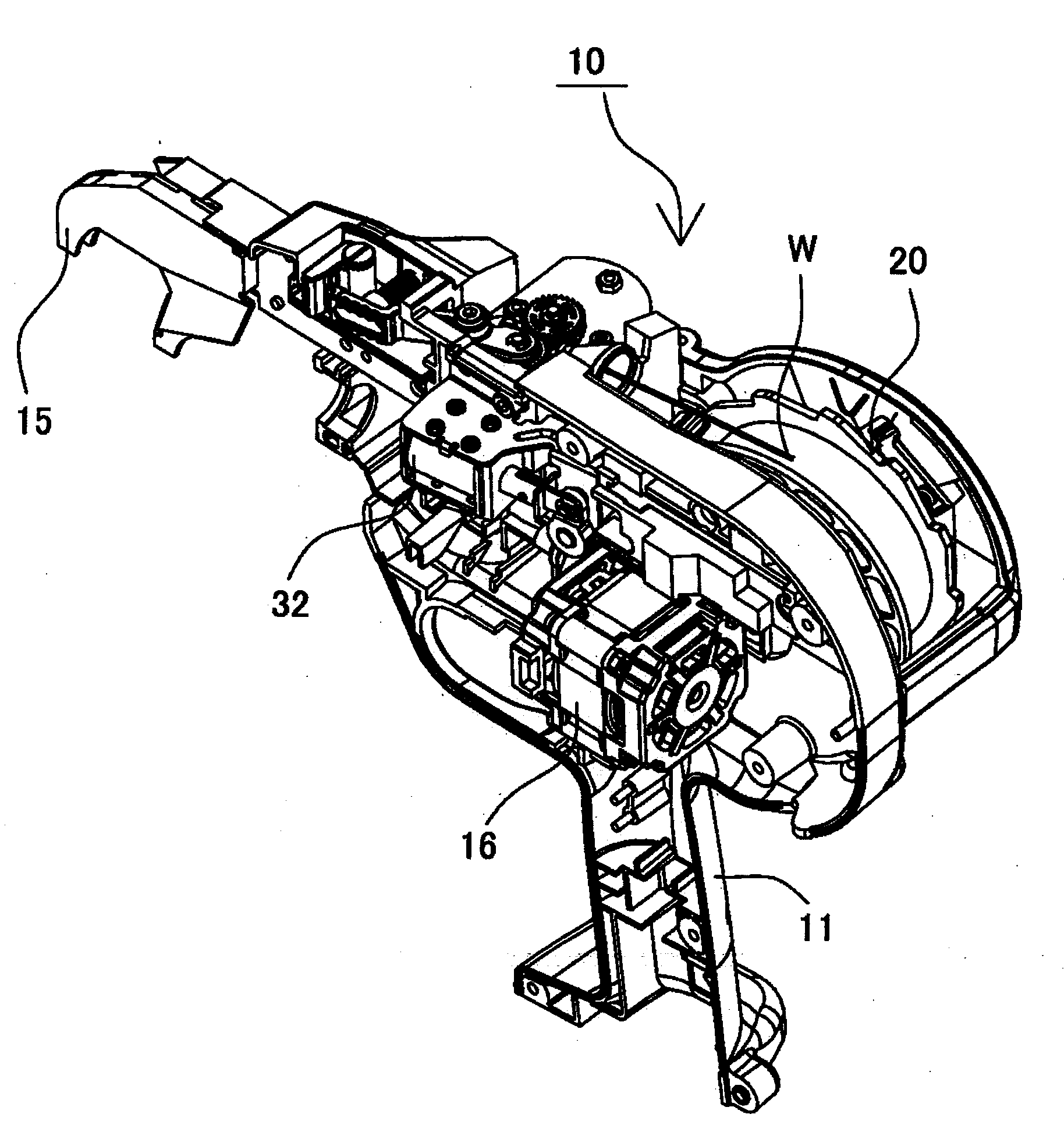
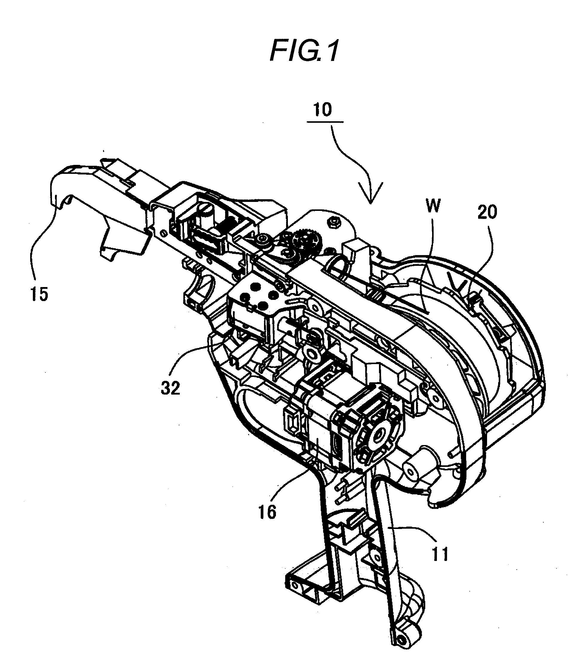
Brake system of wire reel in reinforcing bar binding machine
a technology of reinforcing bars and wire reels, which is applied in the directions of bundling machines, bundling articles, and machine details, etc., can solve the problems of inability to reliably perform braking operation, difficulty in ensuring safety, and increased diameter of wire wound around the wire reels, so as to improve braking performance and save power
- Summary
- Abstract
- Description
- Claims
- Application Information
AI Technical Summary
Benefits of technology
Problems solved by technology
Method used
Image

Examples
second embodiment
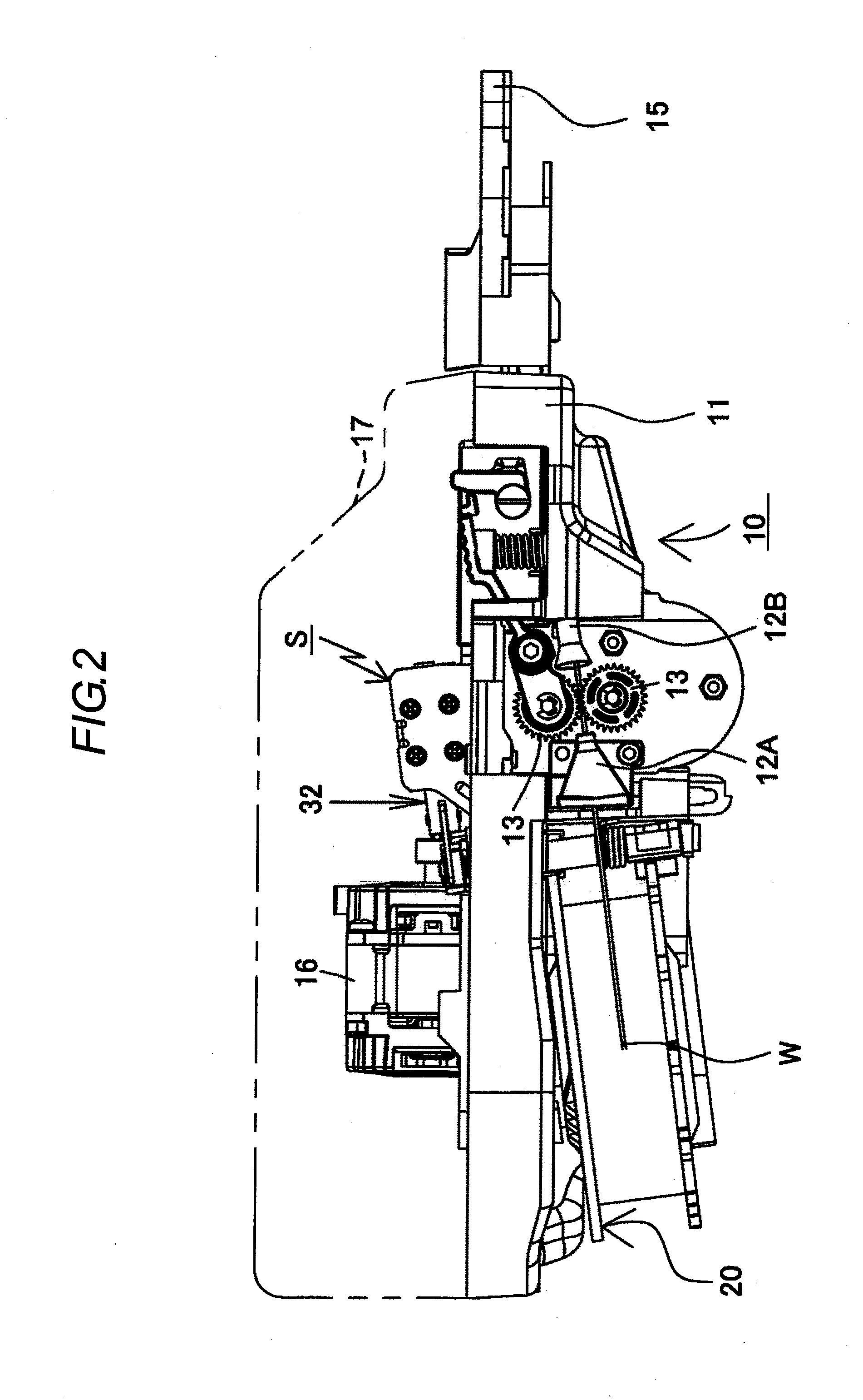
[0109]A second embodiment in which the driving means is changed to an exclusive motor capable of performing normal rotation from a solenoid will be described below with reference to FIGS. 9 and 10. Here, FIG. 9 is a whole perspective view of a brake mechanism in the second embodiment, and FIG. 10 is an exploded perspective view of the brake mechanism shown in FIG. 9. In addition, the same parts as those of the first embodiment are denoted by the same reference numerals. Additionally, FIG. 9 corresponds to FIG. 5 in the first embodiment, and FIG. 10 corresponds to FIG. 6 in the first embodiment.
[0110]In the stopper device of this embodiment, a brake motor (hereinafter referred to as a motor) 60 is fixed to a bracket 58. A gear 61 of the motor 60 meshes with a reduction gear 62 fixed to the shaft 34. In addition, a tubular portion 59 which allows the shaft 34 to be inserted therethrough is arranged at the bracket 58. Additionally, in this embodiment, connecting parts, such as the link...
PUM
| Property | Measurement | Unit |
|---|---|---|
| Length | aaaaa | aaaaa |
| Electric potential / voltage | aaaaa | aaaaa |
Abstract
Description
Claims
Application Information