Intelligent illumniation source particularly for machine vision systems

a machine vision and intelligent technology, applied in the field of camera illumination systems, can solve problems such as reducing the life of the lamp sour

Inactive Publication Date: 2009-11-19
BLENIS JR ROBERT S
View PDF13 Cites 4 Cited by
  • Summary
  • Abstract
  • Description
  • Claims
  • Application Information

AI Technical Summary

Benefits of technology

[0006]The present invention provides apparatus and methods to control an illumination source used with a machine vision system or the like. In a preferred embodiment, light emitting diodes (LEDs) are used to provide high-powered strobed lighting. The LEDs ill

Problems solved by technology

If too much current is used to drive the LEDs, howev

Method used


Image

  • Intelligent illumniation source particularly for machine vision systems
  • Intelligent illumniation source particularly for machine vision systems
  • Intelligent illumniation source particularly for machine vision systems

Examples


Embodiment Construction

[0020]It is to be understood by one of ordinary skill in the art that the present discussion is a description of exemplary embodiments only and is not intended as limiting the broader aspects of the present invention, which broader aspects are embodied in the exemplary constructions.

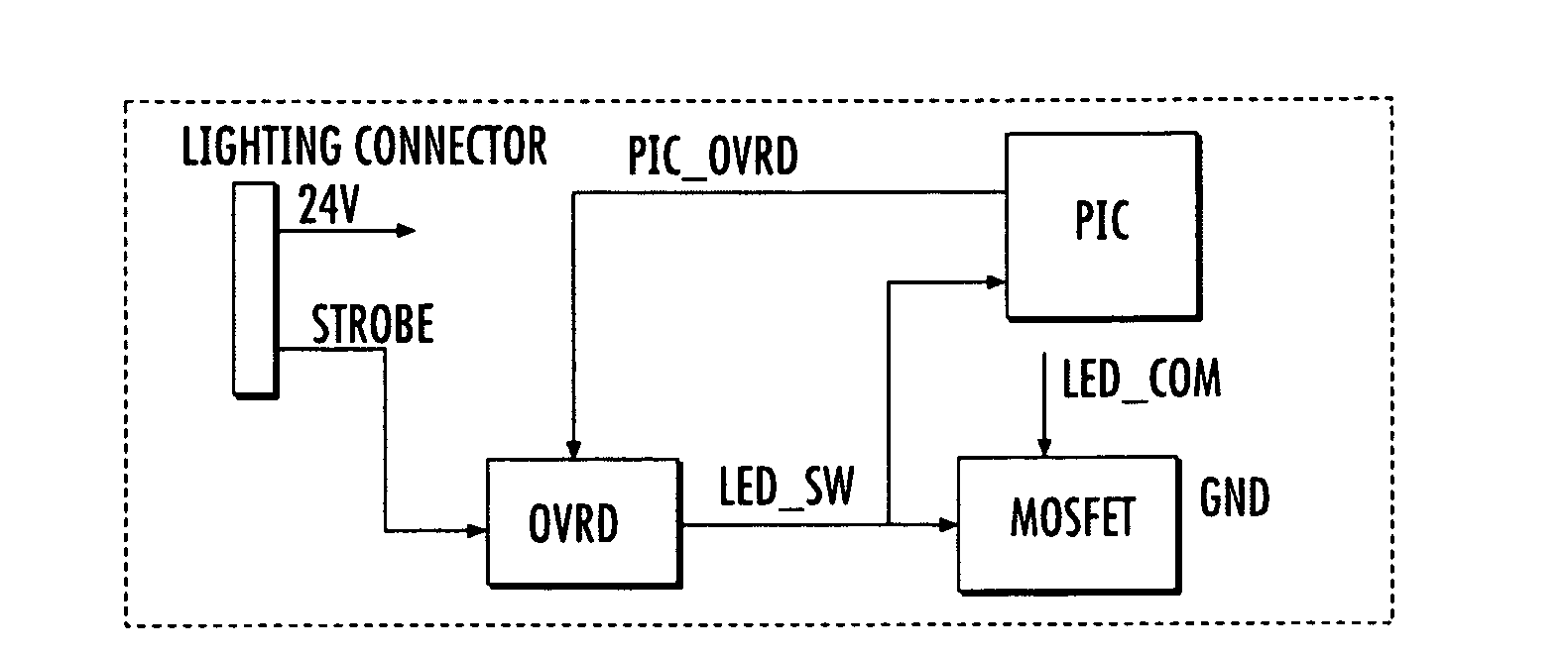
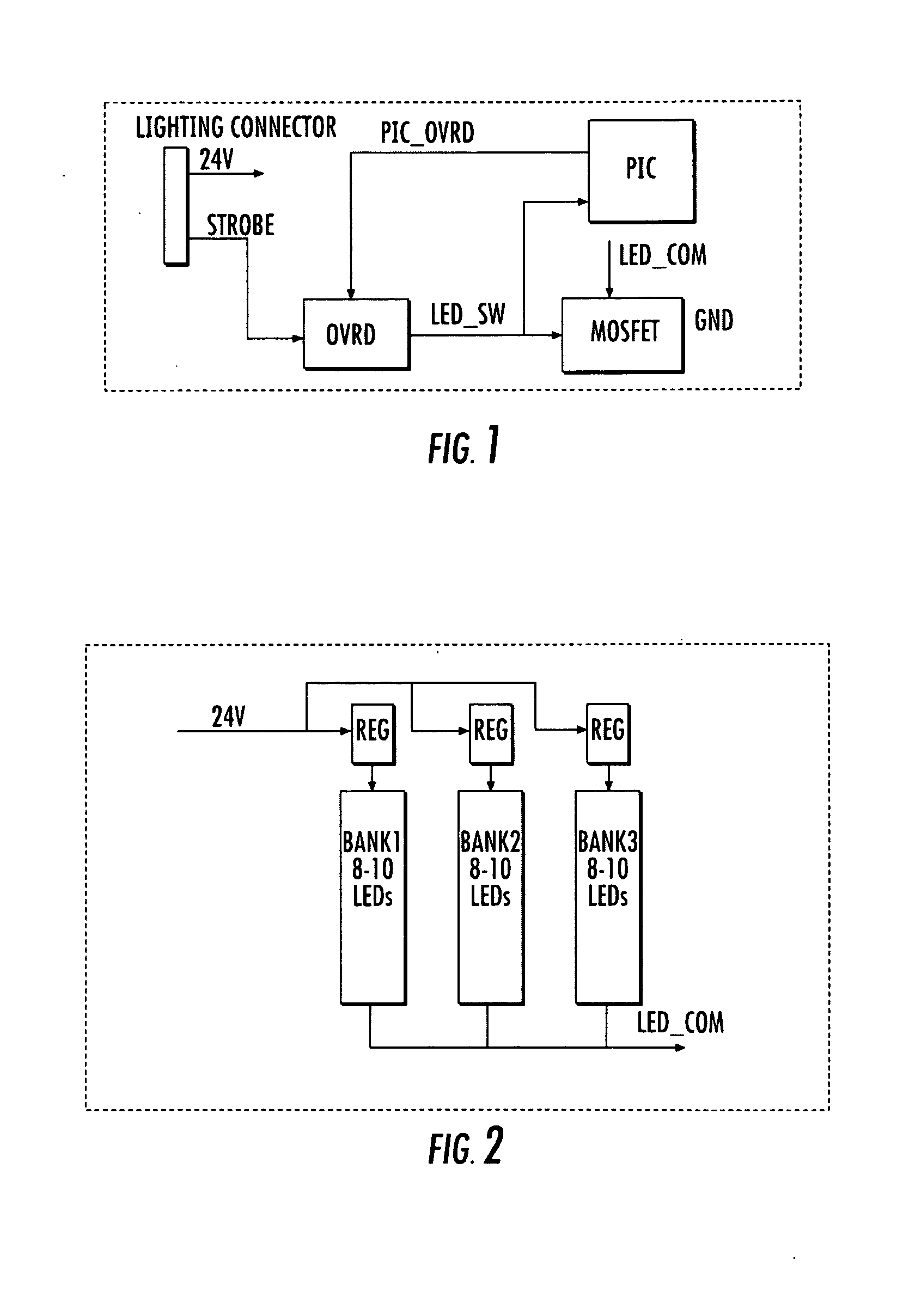
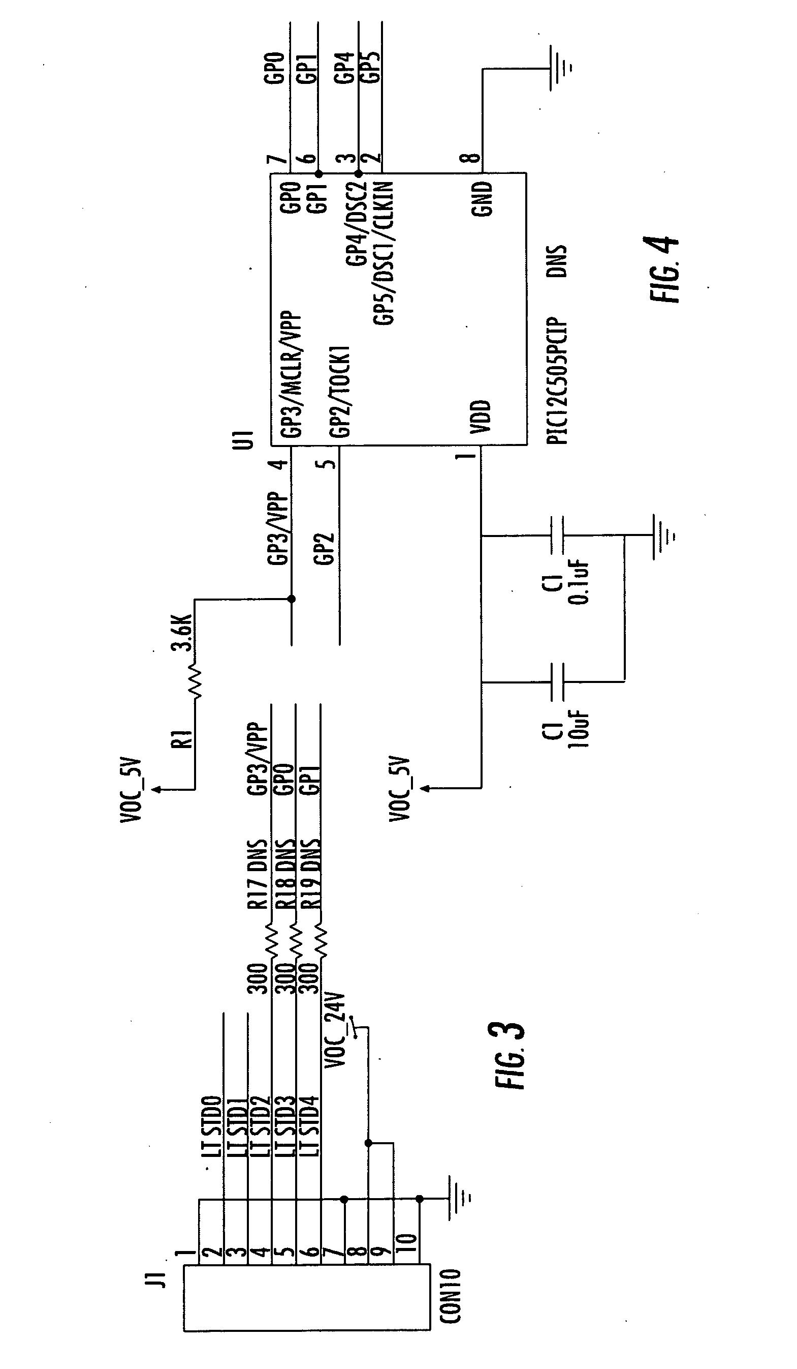
[0021]In accordance with the present invention, circuitry is preferably provided having an “AND” logic gate that receives a user input signal and a supervisory control signal as inputs. In some embodiments, the supervisory control signal will be generated by a microprocessor monitoring the power dissipation level of the circuit and LEDs and the user input signal will be delivered by the camera. A metal-oxide-semiconductor field-effect transistor (MOSFET), or other appropriate switching element, may be controlled by the output of the “AND” logic gate. This electronic switch preferably opens or closes the circuit delivering power to one or more LEDs. In the preferred embodiment, multiple LEDs are assembled...


PUM


Abstract

An illumination apparatus for use with a machine vision camera comprises at least one light source, preferably one or more LEDs, and control circuitry. The control circuitry is operative to receive an illumination command signal and selectively cause application of power to the light source in response thereto. The circuitry includes an electronic switch connected in circuit with the light source. Override circuitry is connected to control operation of the electronic switch so as to cause flow of current through the light source upon receipt of the illumination command signal in a variable manner so as to limit power dissipation.

Description

PRIORITY CLAIM[0001]This application claims the benefit of provisional application Ser. No. 61 / 124,423, filed Apr. 16, 2008, which is relied upon and incorporated herein by reference in its entirety.BACKGROUND OF THE INVENTION[0002]The present invention generally relates to camera illumination systems. More particularly, the invention relates to a light emitting diode (LED) light source for use with machine vision systems.[0003]Machine vision generally relates to the process of using computer systems to visually inspect a process or product. Typical applications of machine vision could include the counting of objects on a conveyor belt, the reading of serial numbers or the inspection of manufactured components. By using computer technology to perform the inspection, errors associated with human inspection can be reduced or eliminated. Also, machine vision allows for higher inspection speeds and, through the use of magnification devices, may allow for the inspection or viewing of ext...

Claims


Application Information

Patent Timeline
IPC IPC(8): H05B37/02H05B45/50
CPCG03B15/02H05B33/089H05B33/0842H05B45/50H05B45/345H05B45/325H05B45/14
Inventor BLENIS, JR., ROBERT S.
Owner BLENIS JR ROBERT S
Why Eureka
Try Eureka