Ultrasonic probe, ultrasonic diagnostic apparatus and ultrasonic endoscopic apparatus

a technology of ultrasonic diagnostic equipment and probe, which is applied in the direction of mechanical vibration separation, catheter, application, etc., can solve the problems of narrow relative bandwidth, increased heat generation at transmission of ultrasonic waves, and increased trailing of ultrasonic pulse waveforms, so as to achieve the effect of not degrading sensitivity and relative bandwidth

Inactive Publication Date: 2009-11-19
FUJIFILM CORP
View PDF8 Cites 9 Cited by
  • Summary
  • Abstract
  • Description
  • Claims
  • Application Information

AI Technical Summary

Benefits of technology

[0012]Accordingly, in view of the above-mentioned points, a purpose of the present invention is to provide an ultrasonic probe in which a balance between basic performance and suppression of heat generation is achieved by suppressing heat generation of the ultrasonic probe without degrading sensitivity and relative bandwidth of the ultrasonic probe in transmission and reception of ultrasonic waves.
[0016]According to one aspect of the present invention, since the vibrator is formed by using the piezoelectric material in which the piezoelectric strain constant d33 not lager than 500 pm / V and the product of the piezoelectric strain constant d33 and a piezoelectric voltage constant g33 is not less than 7000×10−15 m2 / N, the ultrasonic probe can be provided in which a balance between basic performance and suppression of heat generation is achieved by suppressing heat generation of the ultrasonic probe without degrading the sensitivity and relative bandwidth of the ultrasonic probe in transmission and reception of ultrasonic waves.

Problems solved by technology

However, when a material having a large piezoelectric strain constant d33 is selected for further improvement of sensitivity of the ultrasonic probe, there is a problem that the heat generation at transmission of ultrasonic waves increases.
On the other hand, when a material having a large mechanical quality factor Qm is selected for reduction of heat generation, there is a problem that the trailing of the pulse waveform of ultrasonic waves is increased and the relative bandwidth is narrowed.
That is, in the conventional ultrasonic probe, a good valance between the basic performance (sensitivity and relative bandwidth) of the ultrasonic probe and the suppression of heat generation of the ultrasonic probe has not been achieved.

Method used


Image

  • Ultrasonic probe, ultrasonic diagnostic apparatus and ultrasonic endoscopic apparatus
  • Ultrasonic probe, ultrasonic diagnostic apparatus and ultrasonic endoscopic apparatus
  • Ultrasonic probe, ultrasonic diagnostic apparatus and ultrasonic endoscopic apparatus

Examples


first embodiment

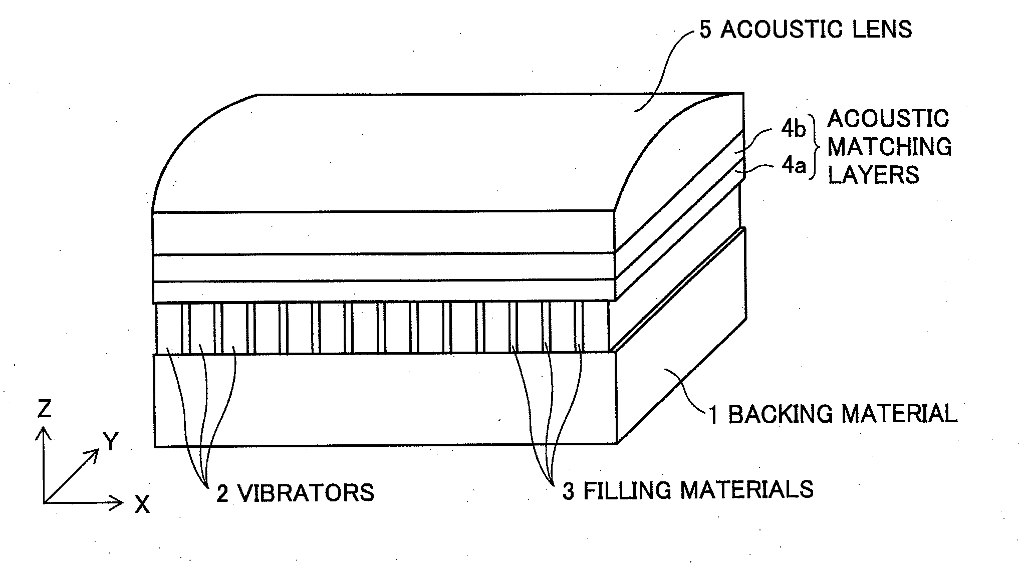
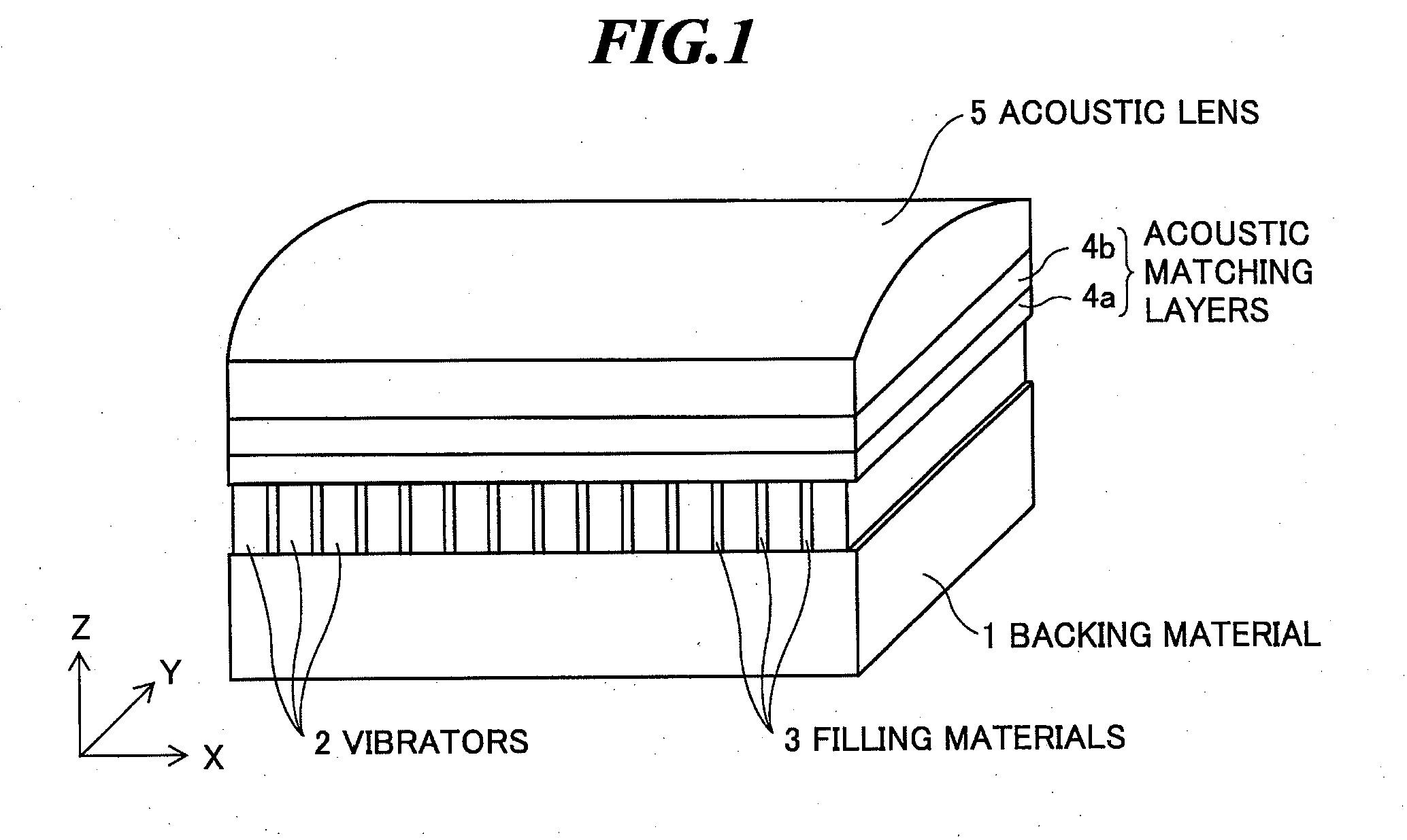
[0033]FIG. 1 is a perspective view schematically showing an internal structure of an ultrasonic probe according to the present invention. The ultrasonic probe is used in contact with an object to be inspected for extracavitary scanning, or used by being inserted into a body cavity of the object for intracavitary scanning.

[0034]As shown in FIG. 1, the ultrasonic probe has a backing material 1, plural ultrasonic transducers (piezoelectric vibrators) 2 provided on the backing material 1, filling materials 3 of epoxy resin or the like filling between and around the plural vibrators 2 for reducing the interference between the vibrators and suppressing the vibration of the vibrators in the lateral direction and allowing the vibrators to vibrate only in the longitudinal direction, at least one acoustic matching layer (two acoustic matching layers 4a and 4b are shown in FIG. 1) provided on the piezoelectric vibrators 2, and an acoustic lens 5 provided on the acoustic matching layers accordi...

second embodiment

[0052]On the other hand, in the second embodiment, as shown in FIG. 7(b), the piezoelectric vibrator has a multilayered structure including plural piezoelectric material layers 2d formed of PZT or the like, a lower electrode layer 2e, internal electrode layers 2f and 2g alternately inserted between the plural piezoelectric material layers 2d, an upper electrode layer 2h, insulating films 2i, a front side electrode 2j, and a rear side electrode (not shown).

[0053]Here, the lower electrode layer 2e is connected to the front side electrode 2j and insulated from the rear side electrode. The upper electrode layer 2h is connected to the rear side electrode and insulated from the front side electrode 2j. Further, the internal electrode layer 2f is connected to the rear side electrode and insulated from the front side electrode 2j by the insulating film 2i. On the other hand, the internal electrode layer 2g is connected to the front side electrode 2j and insulated from the rear side electrod...

fourth embodiment

[0071]FIG. 13 is a schematic diagram showing an appearance of the ultrasonic endoscope using the ultrasonic probe according to the present invention. As shown in FIG. 13, an ultrasonic endoscope 100 includes an insertion part 101, an operation part 102, a connecting cord 103, and a universal cord 104.

[0072]The insertion part 101 is an elongated tube formed of a material having flexibility for insertion into the body of the object. An ultrasonic transducer part (ultrasonic probe) 110 is provided at the leading end of the insertion part 101.

[0073]The operation part 102 is provided at the base end of the insertion part 101, connected to the ultrasonic endoscopic apparatus main body via the connecting cord 103, and connected to a light source unit via the universal cord 104. A treatment tool insertion opening 105 for inserting a treatment tool or the like into the insertion part 101 is provided in the operation part 102.

[0074]FIG. 14 is an enlarged schematic diagram showing the leading ...


PUM


Abstract

An ultrasonic probe in which a balance between basic performance and suppression of heat generation is achieved by suppressing heat generation of the ultrasonic probe without degrading sensitivity and relative bandwidth of the ultrasonic probe in transmission and reception of ultrasonic waves. The ultrasonic probe includes at least one vibrator for transmitting and receiving ultrasonic waves, the at least one vibrator including a piezoelectric material in which a piezoelectric strain constant d33 is equal to or less than 500 pm / V and a product of the piezoelectric strain constant d33 and a piezoelectric voltage constant g33 is equal to or more than 7000×10−15 m2 / N, at least one acoustic matching layer provided on a first surface of the at least one vibrator, and a backing material provided on a second surface opposite to the first surface of the at least one vibrator.

Description

BACKGROUND OF THE INVENTION[0001]1. Field of the Invention[0002]The present invention relates to an ultrasonic probe to be used for extra-cavity scanning or intra-cavity scanning of an object to be inspected. Further, the present invention relates to an ultrasonic diagnostic apparatus including such an ultrasonic probe and an ultrasonic diagnostic apparatus main body, and an ultrasonic endoscopic apparatus including an ultrasonic endoscope having the ultrasonic probe and an ultrasonic endoscopic apparatus main body.[0003]2. Description of a Related Art[0004]In medical fields, various imaging technologies have been developed in order to observe the interior of an object to be inspected and make diagnoses. Especially, ultrasonic imaging for acquiring interior information of the object by transmitting and receiving ultrasonic waves enables image observation in real time and provides no exposure to radiation unlike other medical image technologies such as X-ray photography or RI (radio ...

Claims


Application Information

Patent Timeline
Patent Type & Authority Applications(United States)
IPC IPC(8): A61B8/14B06B1/06
CPCA61B8/12A61B8/445B06B1/0644B06B1/0607
Inventor HYUGA, HIROAKI
Owner FUJIFILM CORP
Why Eureka
Try Eureka