Thermocouple-controlled catether cooling system

a cooling system and catether technology, applied in the field of method and system for controlling fluid flow, can solve the problems of reducing the overall thermal efficiency, affecting the surrounding tissue, and the flow rate may not be sufficient to provide a treatment area on the device,

Active Publication Date: 2009-11-19
MEDTRONIC CRYOCATH LP
View PDF57 Cites 61 Cited by
  • Summary
  • Abstract
  • Description
  • Claims
  • Application Information

AI Technical Summary

Benefits of technology

[0011]The present invention also provides a method for controlling fluid flow through a medical device, including circulating a coolant through the medical device; measuring a first temperature at a distal portion of the medical device; measuring a second temperature at a position proximal of the distal portion of the medical device; and adjusting the circulation of coolant based at least in part upon the first and second temperature measurements. The method may also include determining a pressure measurement or value based upon at least one of the first and second temperature measurements. Further, the first temperature measurement may be performed by a first temperature sensor, and the second temperature measurement may be performed by a second temperature, the method further including measuring an electrical resistance or impedance between the first and second temperature sensors; and determining the presence of a leak in the medical device

Problems solved by technology

For example, for a fixed flow rate and a low thermal load on a device, a flow rate may become excessive, resulting in a portion of the circulating fluid failing to change phase from a liquid/solid to a gas, and thereby reducing the overall thermal efficiency and affect on the surrounding tissue.
Moreover, at a high heat load, a s

Method used


Image

  • Thermocouple-controlled catether cooling system
  • Thermocouple-controlled catether cooling system
  • Thermocouple-controlled catether cooling system

Examples


Embodiment Construction

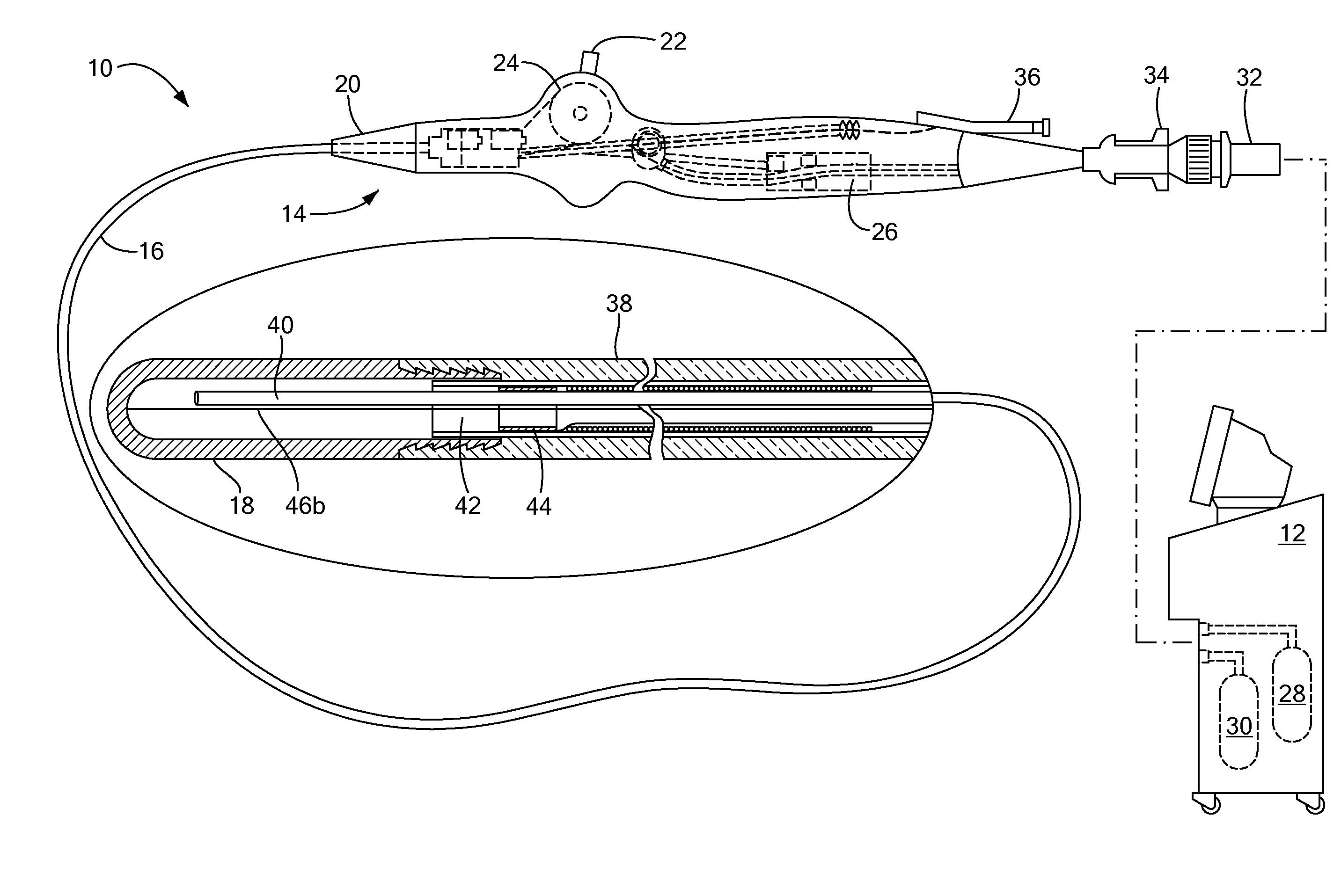
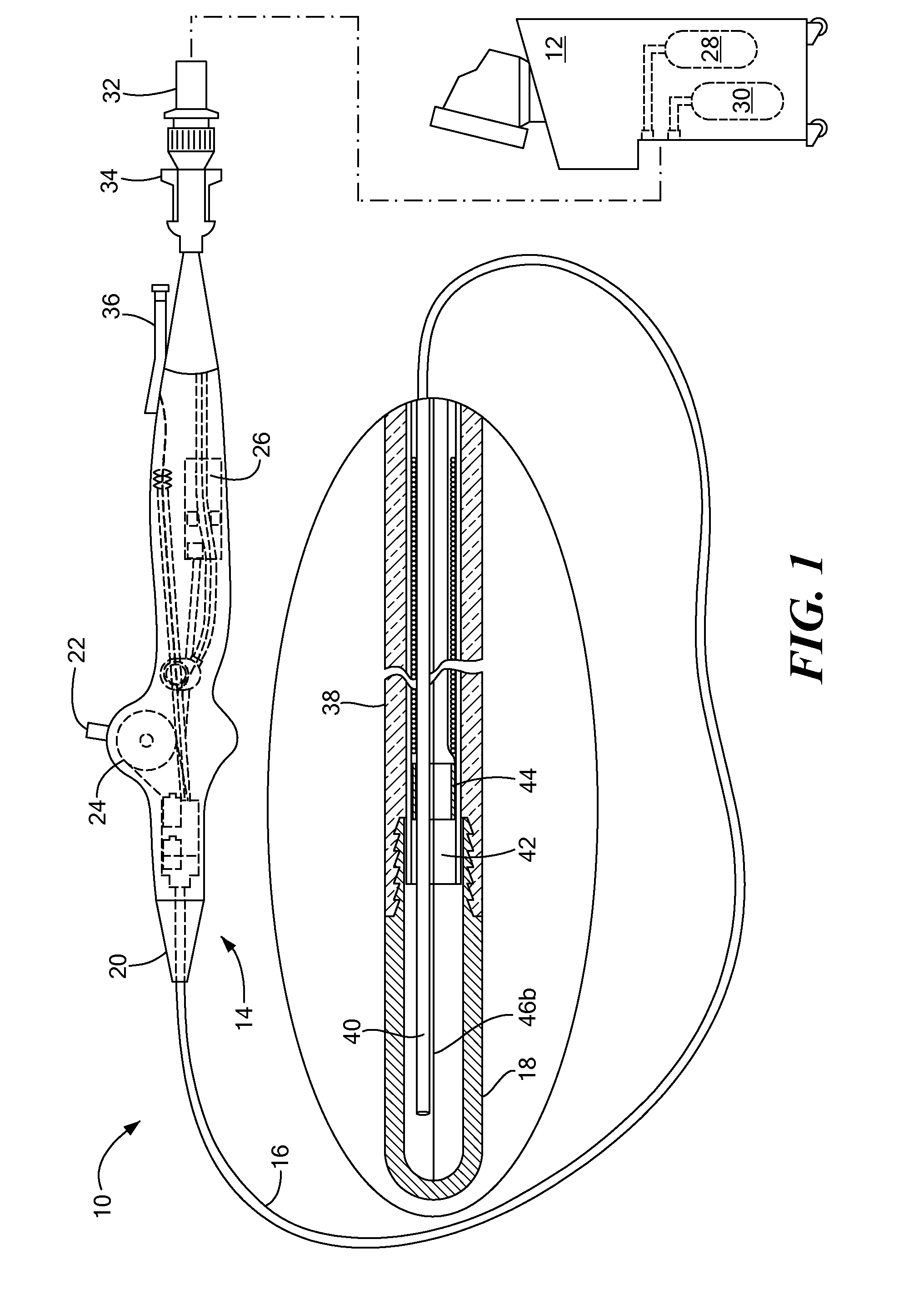
[0018]The present invention provides an improved apparatus and method of monitoring and controlling the circulation of a coolant through a medical device such as an intravascular catheter or surgical probe. Referring now to the drawing figures in which like reference designators refer to like elements, there is shown in FIG. 1 an exemplary system suitable for thermally treating tissue, generally designated as 10. The system 10 includes a console 12 coupled to a medical treatment device 14, where the treatment device 14 may be a medical probe, a catheter, a balloon-catheter, as well as other devices commonly known in the art, such as devices able to pass easily through blood vessels and heart valves and able to thermally affect tissue, for example. Of course, the present invention is compatible with catheters or probes that are equally adaptable for both endovascular and surgical procedures involving thermal treatment applications.

[0019]In particular, the system 10 may include an elo...


PUM


Abstract

The present invention provides a medical system, including a catheter defining an injection lumen, a chamber in fluid communication with the injection lumen, and an exhaust lumen in fluid communication with the chamber; a first temperature sensor positioned in the exhaust lumen proximal to the chamber; a second temperature sensor positioned in the chamber; and a console in electrical communication with the first and second temperature sensors, the controller modifying coolant flow through the medical device based at least in part upon a signal received from the first and second temperature sensor. The system may further include a thermally-conductive element circumscribing a substantial portion of the exhaust lumen proximal to the chamber, where the first temperature sensor is mounted to the thermally-conductive element, and the thermally-conductive element may include at least one of a braid, coil, and band.

Description

CROSS-REFERENCE TO RELATED APPLICATION[0001]n / aSTATEMENT REGARDING FEDERALLY SPONSORED RESEARCH OR DEVELOPMENT[0002]n / aFIELD OF THE INVENTION[0003]The present invention relates to a method and system for controlling fluid flow in a medical device, and in particular, towards controlling the flow of a coolant in an intravascular catheter via temperature feedback.BACKGROUND OF THE INVENTION[0004]The use of fluids with low boiling temperatures, or cryogens, is becoming increasingly explored and employed in the medical and surgical field. Of particular interest is the use of catheter based devices employing the flow of cryogenic fluids therein to selectively freeze or otherwise thermally affect targeted tissues within the body. Catheter based devices are desirable for various medical and surgical applications in that they are relatively non-invasive and allow for precise treatment of localized discrete tissues that are otherwise inaccessible. Catheters may be easily inserted and navigate...

Claims


Application Information

Patent Timeline
IPC IPC(8): A61B18/02A61F7/12A61M25/01
CPCA61B18/02A61B2018/00023A61B2018/0022A61M25/0136A61B2018/00821A61B2018/0212A61B2018/0262A61B2018/00797
Inventor LALONDE, JEAN-PIERREWITTENBERGER, DANABBOUD, MARWANCIOBOTARU, CONSTANTIN BOGDANSABBAGHE-KERMANI, RAMIN
Owner MEDTRONIC CRYOCATH LP
Why Eureka
Try Eureka