Light Scanning Photoelectric Switch

a light scanning and photoelectric switch technology, applied in the direction of identification means, distance measurements, instruments, etc., can solve the problems of difficult installation of light scanning photoelectric switches, complicated setting, inconvenient for users, etc., and achieve the effect of reducing the size of photoelectric switches

Active Publication Date: 2009-11-19
KEYENCE
View PDF21 Cites 17 Cited by
  • Summary
  • Abstract
  • Description
  • Claims
  • Application Information

AI Technical Summary

Benefits of technology

[0029]According to this aspect of the present invention, it is possible to reduce the size of the photoelect...

Problems solved by technology

However, such a mat switch or a light curtain has a fixed detection area which depends on a shape of an individual product, and it is necessary to prepare a number of products of different shapes, which is inconvenient for a user.
However, the setting itself is complicated because...

Method used


Image

  • Light Scanning Photoelectric Switch
  • Light Scanning Photoelectric Switch
  • Light Scanning Photoelectric Switch

Examples


first embodiment

[0044]Hereinafter, one embodiment of the present invention will be described with reference to the drawings.

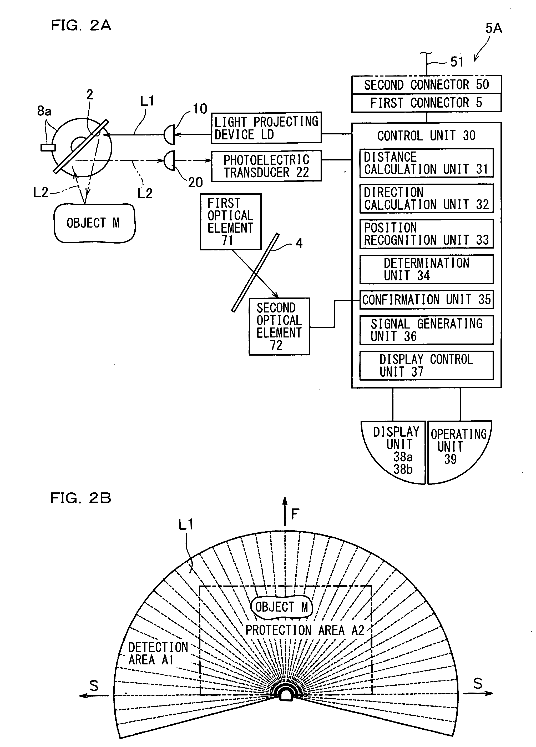
[0045]A light scanning photoelectric switch according to the present embodiment, for example, is connected to an external device such as a robot, and outputs a safety signal indicating that operation of the connected external device is either enabled or disabled. For example, when an object M such as a human body is detected within a protection area A2 that has been previously set as shown in FIG. 2B, the photoelectric switch of the present embodiment, in a predetermined mode, outputs an operation disable signal to prohibit (disable) the operation of the external device connected to the photoelectric switch. The protection area A2 is previously set within a detection area A1 and recorded.

Optical Path

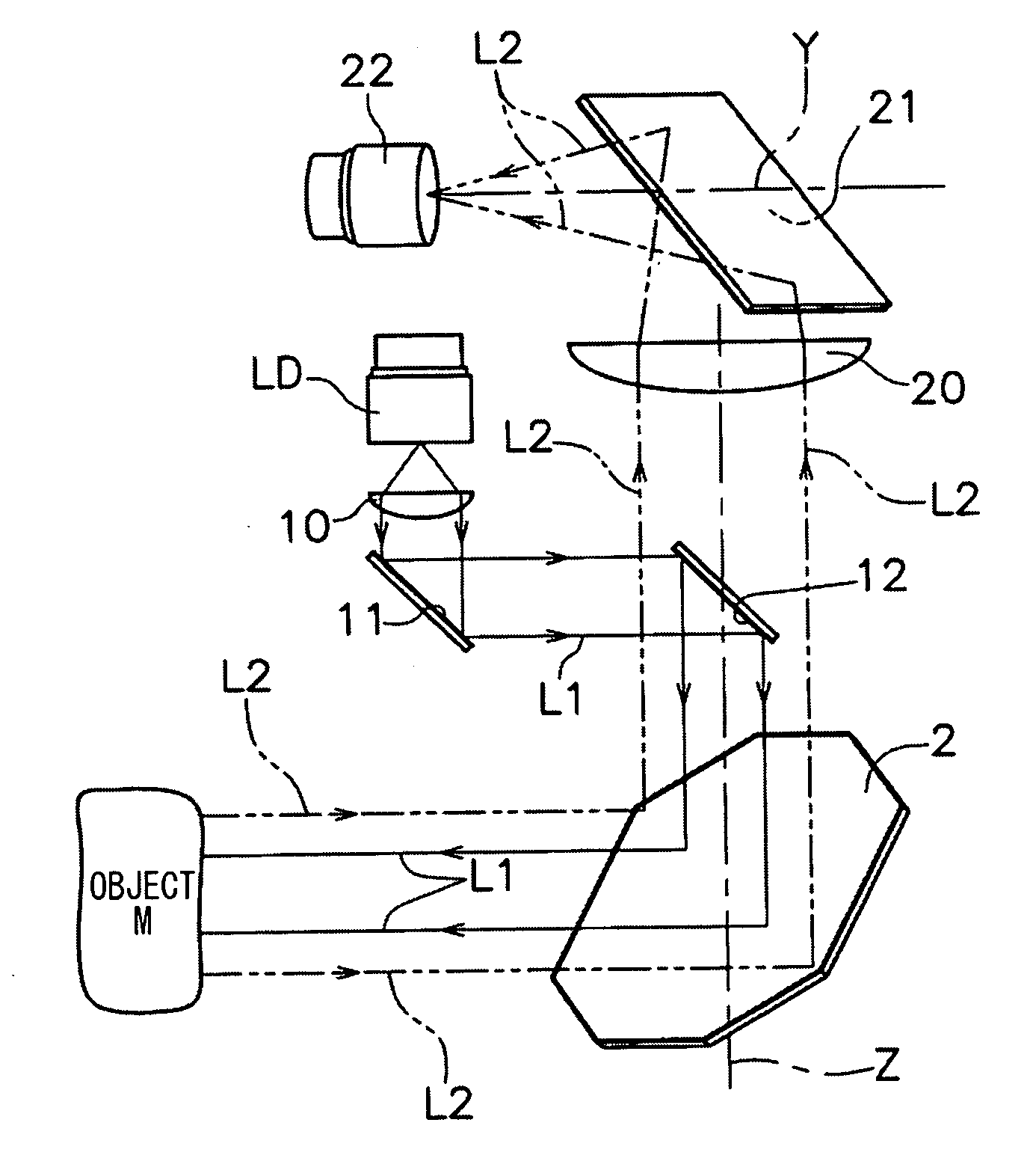
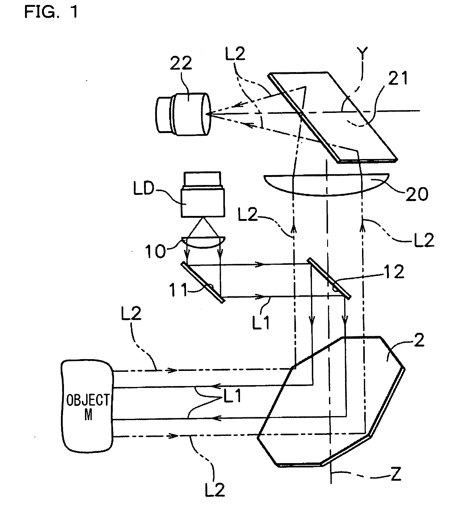
[0046]The photoelectric switch of the present embodiment detects the object M by, for example, scanning light such as a laser beam. An optical system is first described.

[0047]Light...


PUM


Abstract

This invention provides a light scanning photoelectric switch with which various settings of the light scanning photoelectric switch such as setting of a protection area can be easily set. The light scanning photoelectric switch includes: a display unit having a display screen that displays information including at least one of a status of a safety function of the light scanning photoelectric switch, and information of a failure status; and an operating unit provided in vicinity of the display unit, and for switching the information displayed in the display screen to different one of the safety signal, the result of the determination, setting contents of the light scanning photoelectric switch, the status of the safety function of the light scanning photoelectric switch, and the information of the failure status.

Description

CROSS-REFERENCE TO RELATED APPLICATIONS[0001]The present application claims foreign priority based on Japanese Patent Application No. 2008-126851, filed May 14, 2008, the contents of which is incorporated herein by reference.BACKGROUND OF THE INVENTION[0002]1. Field of the Invention[0003]The present invention relates to a light scanning photoelectric switch.[0004]2. Description of the Related Art[0005]Conventionally, there has been proposed a scanning device that detects, using light such as laser, whether or not an object is present within a predetermined area that has been previously set (see Japanese Unexamined Patent Publication No. 4-310890 (Abstract), Japanese Unexamined Patent Publication No. 3-175390 (FIG. 1), and U.S. Pat. No. 5,455,669 (FIG. 4)).[0006]A light scanning photoelectric switch is a so-called safety scanner or safety laser scanner, and scans over a detection area with light such as laser, receives the scanning light that has been reflected within the detection a...

Claims


Application Information

Patent Timeline
IPC IPC(8): G06F15/00G01B11/14G09F9/33
CPCG01B11/03
Inventor OH, CHORYON
Owner KEYENCE
Why Eureka
Try Eureka