LED Grow Light Method and Apparatus

a technology of led grow light and grow light, which is applied in the field of improved light emitting diodes (led) grow light method and apparatus, can solve the problems of high cost of manufacture and operation, excessive heat and noise, and high cost of thousands of dollars, and achieve the effect of improving plant growth

Inactive Publication Date: 2009-11-26
HESS RYAN
View PDF6 Cites 111 Cited by
  • Summary
  • Abstract
  • Description
  • Claims
  • Application Information

AI Technical Summary

Benefits of technology

[0013]The LED grow light apparatus of the present invention provides an improved grow light fixture that may be used for the replacement of high intensity discharge (HID) lamp fixtures used for growing plants. The inventive apparatus includes a housing containing a plurality of both red and blue high power LEDs mounted to a circuit board, and powered by an onboard power supply. The combination of red and blue LEDs has been determined to provide an ideal light spectrum for growing plants. Control circuitry may include separate, infinitely variable controls to enable independent adjustment of the red and blue LED light output. A plurality of thermal vias made of copper or other thermally conductive material preferably extend through the circuit board to conduct heat from the LEDs to a heat sink mounted on the back of the circuit board, and a fan may be used to vent the heat to the outside of the housing. The housing is mounted an appropriate distance above a plant in a growth media to provide user-controlled lighting for enhanced plant growth.

Problems solved by technology

Typical grow light fixtures use high intensity discharge (HID) lamps, which can be costly to manufacture and operate.
For example, many HID grow lamps cost thousands of dollars, may consume on the order of 400-1000 watts of electricity, and often produce excessive amounts of heat and noise.

Method used


Image

  • LED Grow Light Method and Apparatus
  • LED Grow Light Method and Apparatus
  • LED Grow Light Method and Apparatus

Examples


Embodiment Construction

[0052]Referring to FIGS. 1 through 6, wherein like reference numerals refer to like components in the various views, there is illustrated therein a new and improved LED grow light apparatus, generally denominated 11 herein.

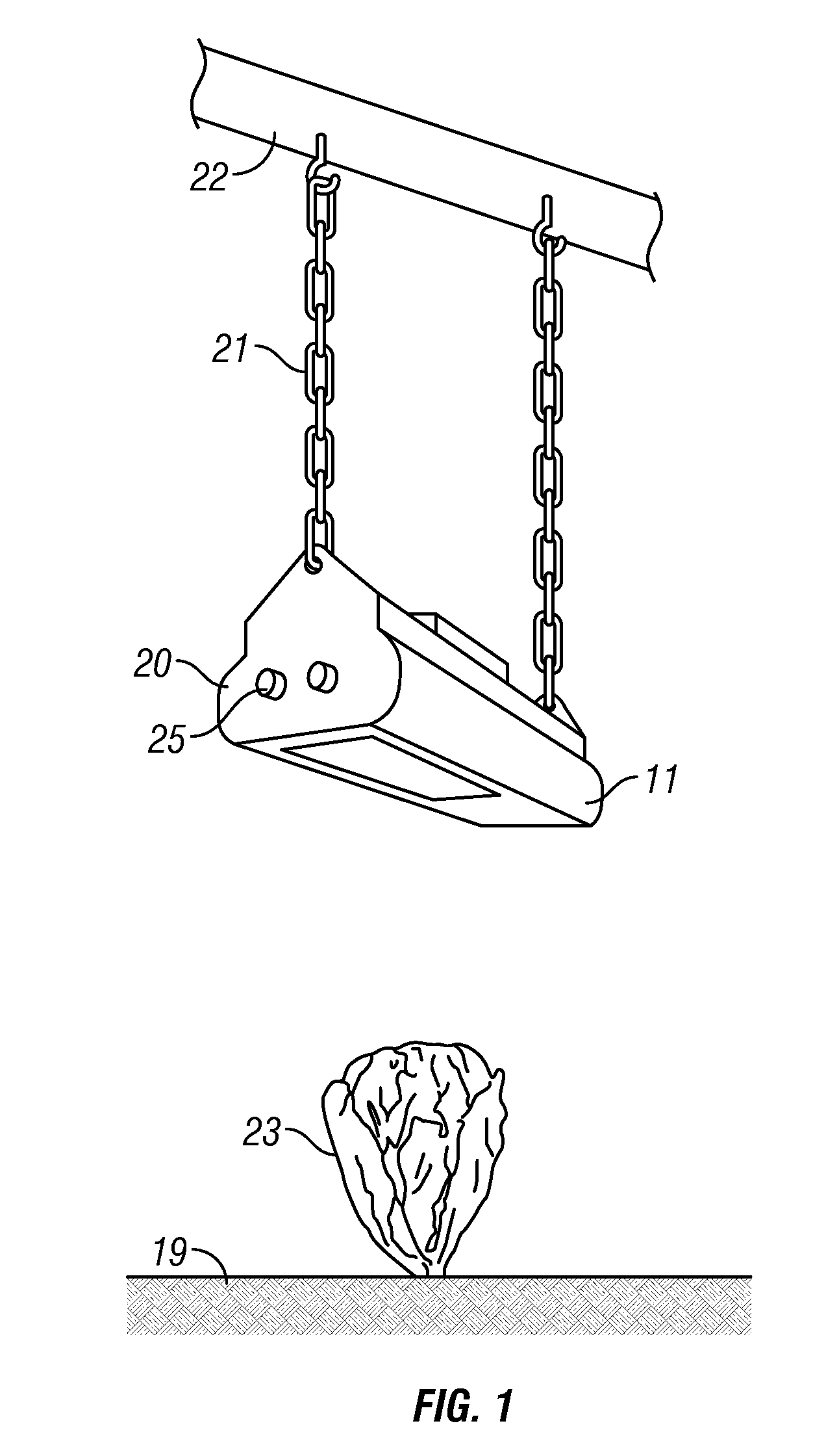
[0053]FIG. 1 is a perspective view of an LED grow light apparatus of the present invention in use. Light fixture 11 may be mounted to an existing support beam 22 or other structure by chains 21. Red and blue light spectrum intensity may be controlled by control knobs 25 preferably mounted on end plate 20, and light is emitted onto plant 23 in grow media 19.

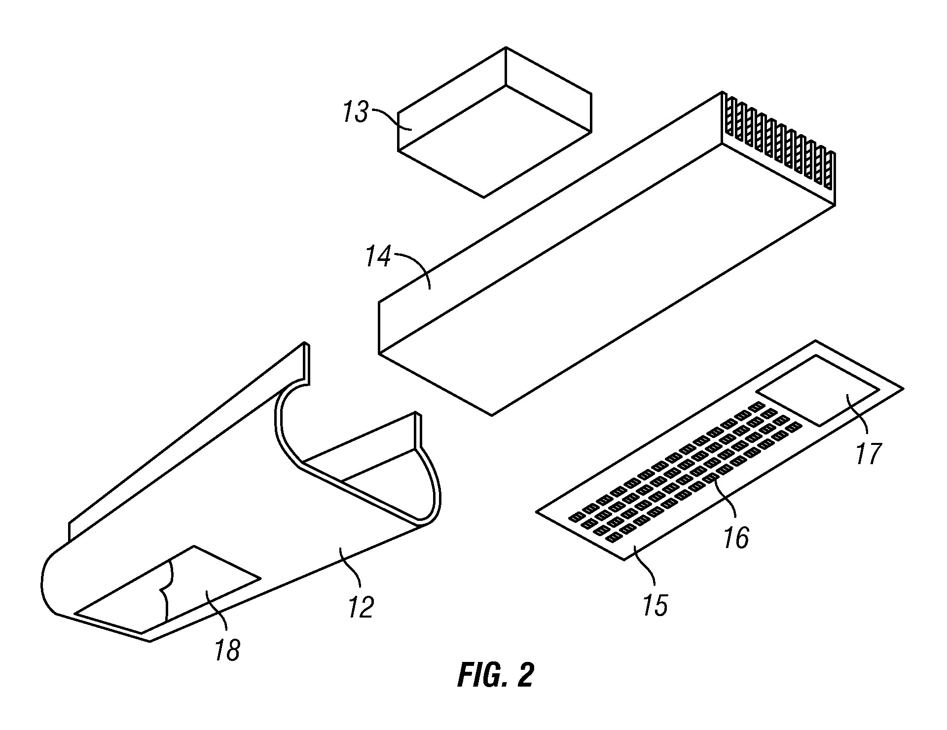
[0054]FIG. 2 is an exploded view of an LED grow light apparatus of this invention. The light fixture 11 includes a plurality of high power (e.g., 2 watts or more) light emitting diodes 16 secured to a printed circuit board 15. For example, 40 high power red LEDs (heaving a peak wavelength of 635 nm) and 16 high power blue LEDs (having a peak wavelength of 450 nm) such as Xlamp LEDs manufactured by Cree may be ar...


PUM


Abstract

A grow light fixture that may be used for the replacement of high intensity discharge (HID) lamp fixtures used for growing plants includes a housing containing a plurality of both red and blue high power LEDs mounted to a circuit board, and powered by an onboard power supply. Control circuitry may include separate, infinitely variable controls to enable independent adjustment of the red and blue LED light output. A plurality of thermal vias made of copper or other thermally conductive material extend through the circuit board to conduct heat from the LEDs to a heat sink mounted on the back of the circuit board, and a fan may be used to vent the heat to the outside of the housing. The housing is mounted an appropriate distance above a plant in a growth media to provide user-controlled lighting for enhanced plant growth.

Description

CROSS REFERENCE TO RELATED APPLICATIONS[0001]The present application claims the benefit of the filing date of U.S. Provisional Patent Application Ser. No. 61 / 128,786, filed May 23, 2008.STATEMENT REGARDING FEDERALLY SPONSORED RESEARCH OR DEVELOPMENT[0002]Not applicable.REFERENCE TO A MICROFICHE APPENDIX[0003]Not applicable.TECHNICAL FIELD[0004]The present invention relates generally to electric lamp fixtures used for growing plants, and more particularly to an improved light emitting diode (LED) grow light method and apparatus.BACKGROUND INFORMATION AND DISCUSSION OF RELATED ART[0005]Typical grow light fixtures use high intensity discharge (HID) lamps, which can be costly to manufacture and operate. For example, many HID grow lamps cost thousands of dollars, may consume on the order of 400-1000 watts of electricity, and often produce excessive amounts of heat and noise.[0006]U.S. Pat. No. 6,921,182 to Anderson, Jr., et al. discloses an LED lamp for enhancing commercial and home plan...

Claims


Application Information

Patent Timeline
Patent Type & Authority Applications(United States)
IPC IPC(8): A01G7/00F21L4/02A01G9/20
CPCA01G9/26A01G7/045A01G9/249Y02P60/14Y02A40/25
Inventor HESS, RYAN
Owner HESS RYAN
Why Eureka
Try Eureka