[0012]With a region of the shaft forming a
handle, an easy and a convenient, for the user, handling of the borehole cleaning device is insured. The shaft is hollow over its entire longitudinal extent so that the hollow space of the shaft opens into the front opening, on one hand, and into the suction opening, on the other hand. Thus, the hollow space connects the suction opening with the front opening at the first end of the shaft. Even when an outer cover, which is placed on the constructional component, is provided, no underpressure, which can adversely affect the cleaning effect, is produced during the reciprocating movement of the device for cleaning the borehole.
[0013]Advantageously, the suction opening is provided the second end of the shaft opposite the front opening, which provides for an advantageous manufacturing of the shaft and, thus, of the device itself. The shaft advantageously is
cut to a desired length from a tubular piece as a half-finished piece, with open ends forming the suction and front openings without any additional treatment of the shaft. Because the shaft does not have any radially opening bore, the shaft has a sufficiently stable shape even at a small wall thickness. In addition, no or very small air turbulence, which might hinder the air flow within the shaft, is produced. Thus, during the use of the device, there is a high-volume flow of the environmental air in the borehole, which insures an advantageous borehole cleaning.
[0015]Advantageously, the region of the shaft adjacent to the suction opening has, at least in some regions, a shaped profile, which provides for an easy and ergonomically advantageous holding of the device. The shaped profile of the
handle section improves handling of the borehole cleaning device. The shaped profile, which is formed, e.g., as serrations, is provided, e.g., directly on the outer side of the shaft region adjacent to the suction opening. Alternatively, the shaped profile can be provided on a separate part that is securable adjacent to the second end of the shaft, e.g., by being glued, shrink-mounted, or pinned on. The separate part is formed, e.g., of a plastic material.
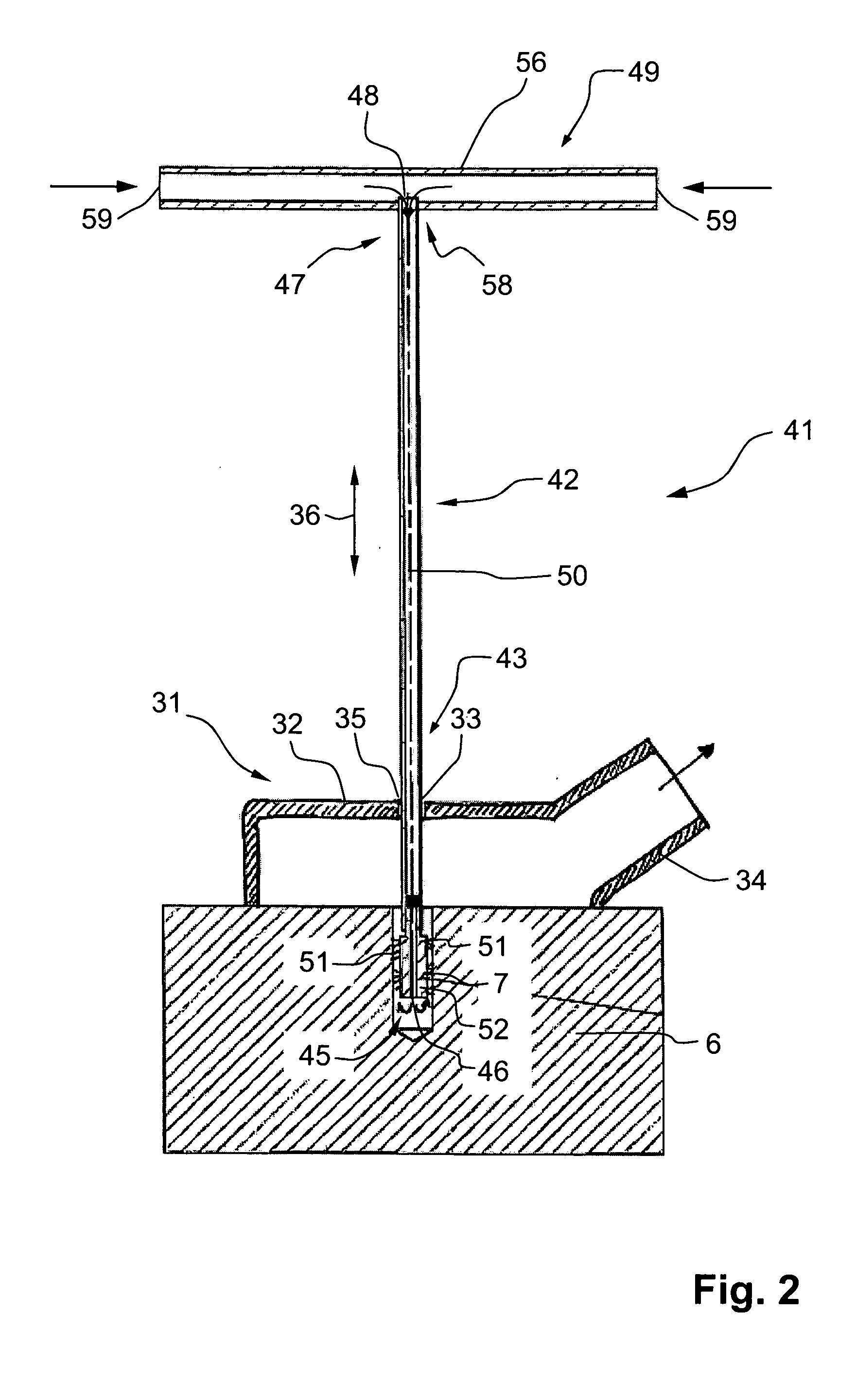
[0017]Advantageously, the through-opening is provided with sealing elements projecting radially inwardly. The sealing elements prevent an undesirable release of the drilling dust into environment during the operation of the borehole cleaning device in the region of the suction head with the through-opening.
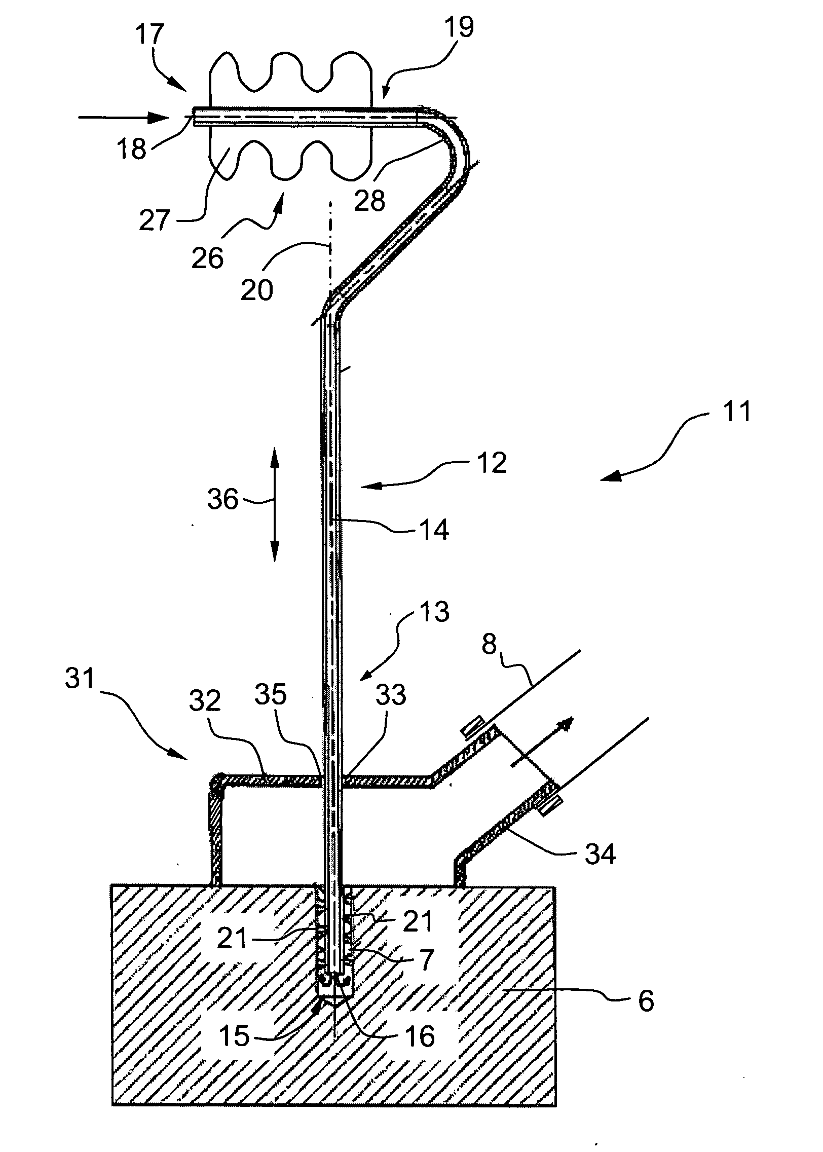
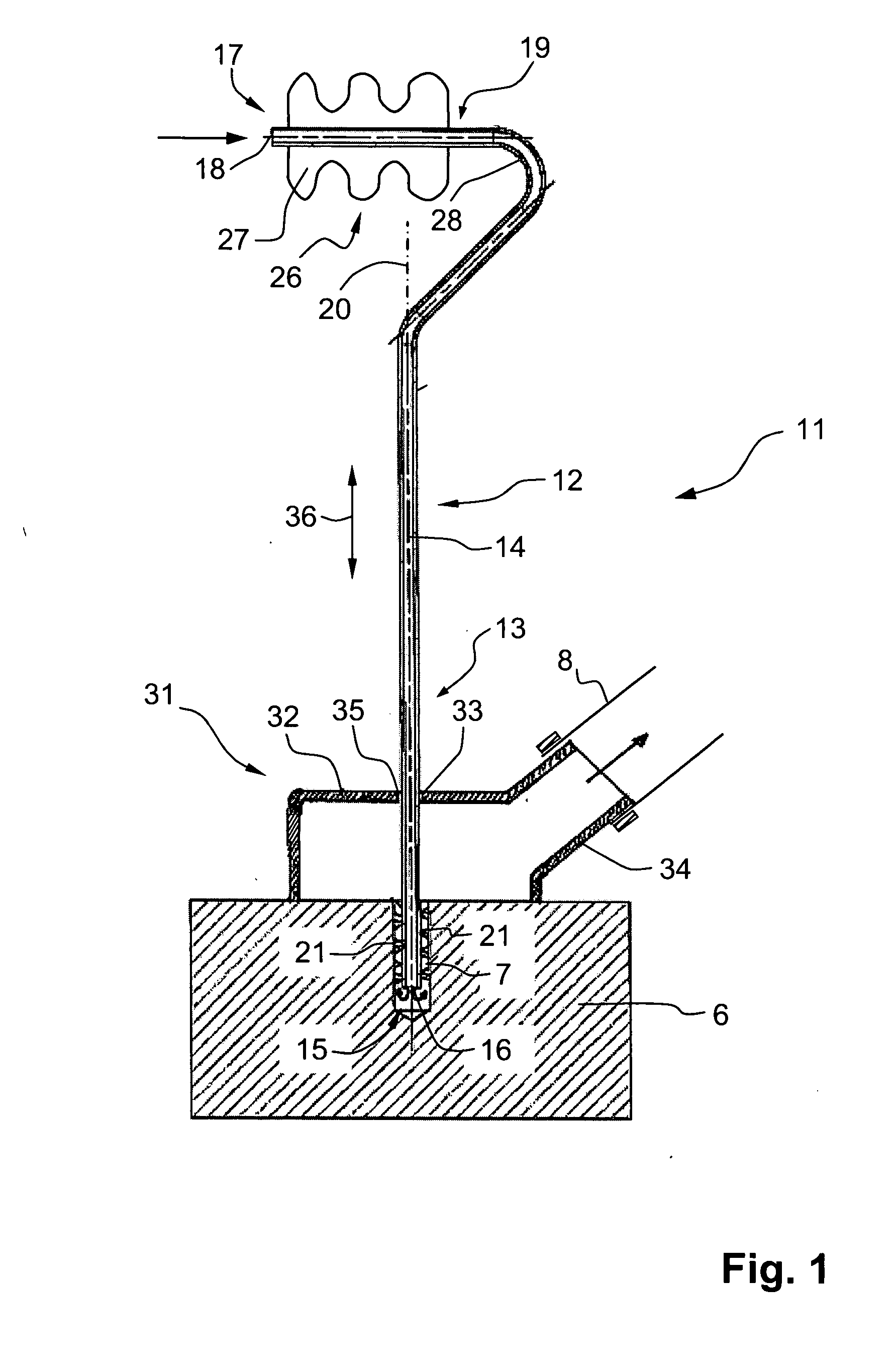
[0019]A hose of a vacuum source is connected with the connection element of suction head, and the suction head is positioned over the borehole. The shaft is introduced with its first end, i.e., with
its region provided with
brush members, into the borehole through the through-opening of the suction head. Alternatively, the region of the shaft provide with the brush members can be displaceably held but without a possibility of being lost, on the suction head. After positioning of the suction head, the region of the shaft with brush members is pushed into the borehole, and the vacuum source is actuated. After the region of the shaft adjacent to the suction opening and forming the handle has been grasped, the device is manually reciprocated for a certain time to and from the constructional component or the constructional part, whereby the brush members, which were inserted in the borehole, clean the borehole. Because of a vacuum created in the suction head and the borehole by the vacuum source, the environmental air passively flows through the shaft in the borehole and entrains the brushed-off drilling dust and the remaining drilling dust and
moisture away. This insures an advantageous cleaning of the borehole, which insures adhesion of the hardenable
mass to the borehole wall and, thereby, an advantageous anchoring of a chemically anchorable fastening element.

