Heated Garment
a technology of electric heating and garments, applied in the direction of secondary cell servicing/maintenance, cell components, light source combinations, etc., can solve the problems of limited range of motion, and person being weighted down with very limited range of motion
- Summary
- Abstract
- Description
- Claims
- Application Information
AI Technical Summary
Benefits of technology
Problems solved by technology
Method used
Image
Examples
second embodiment
[0074]FIG. 10B is a cross-sectional view of a portion of the present invention showing garment layers 1002. In this embodiment a water resistant shell garment is included over the outside of the garment layers 1000 such as is employed in the Storm Chaser™ 3-in-1 Jacket mentioned above. The shell has a shell garment fabric 1008 that may be of a water resistant nylon having a shell garment outer face 1006. The shell garment fabric 1006 is preferably detachably affixed to the garment fabric outer layer 1004 at the periphery of the garment such as in the central zipper region, collar and cuffs.
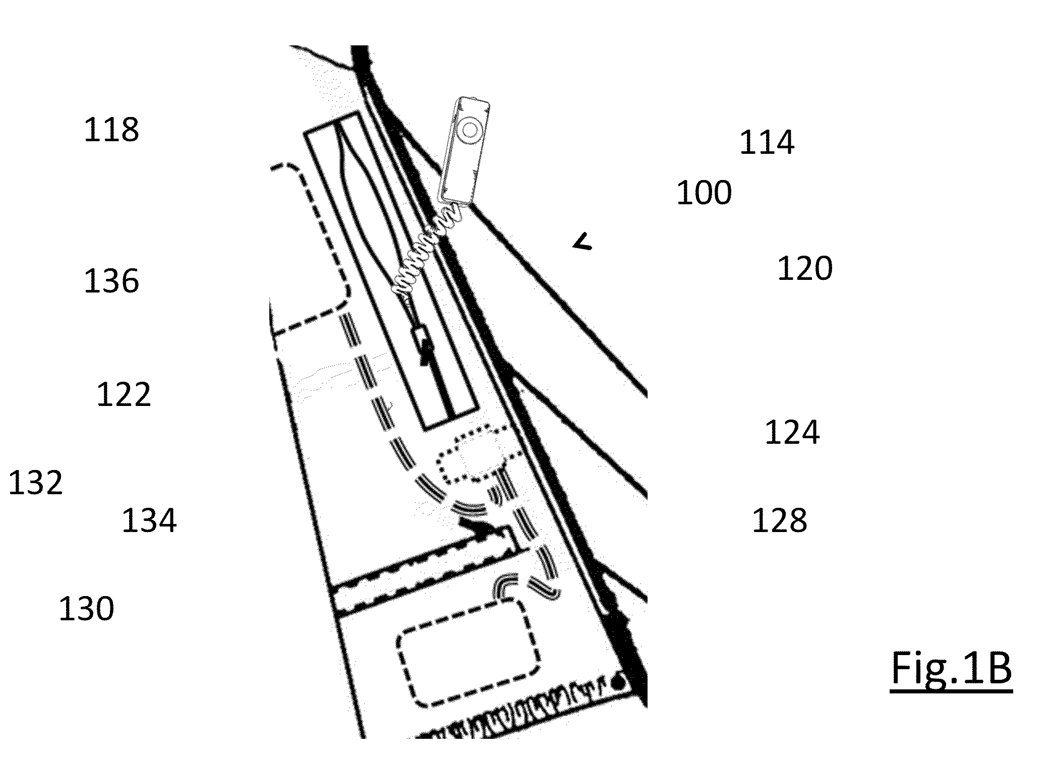
[0075]FIGS. 11, 12A and 12B shows schematic views of the controller pocket zipper 122 in accordance with the preferred embodiment of the present invention as shown in FIG. 1B. The controller pocket zipper 122 has a controller pocket zipper top region 1108 where the controller pocket zipper pull 1101 is located when the zipper is fully closed. The controller pocket zipper 122 has a controller pocke...
third embodiment
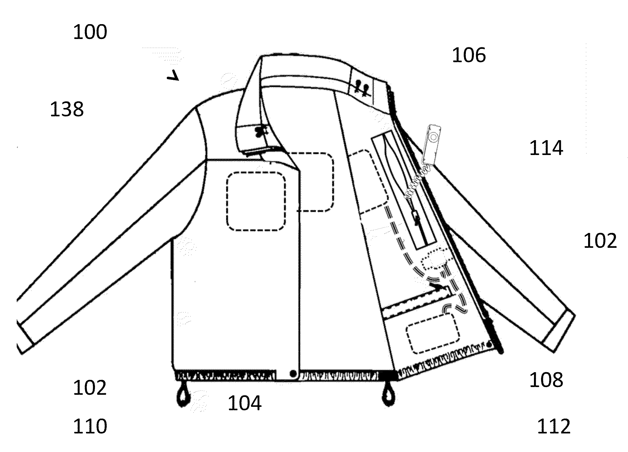
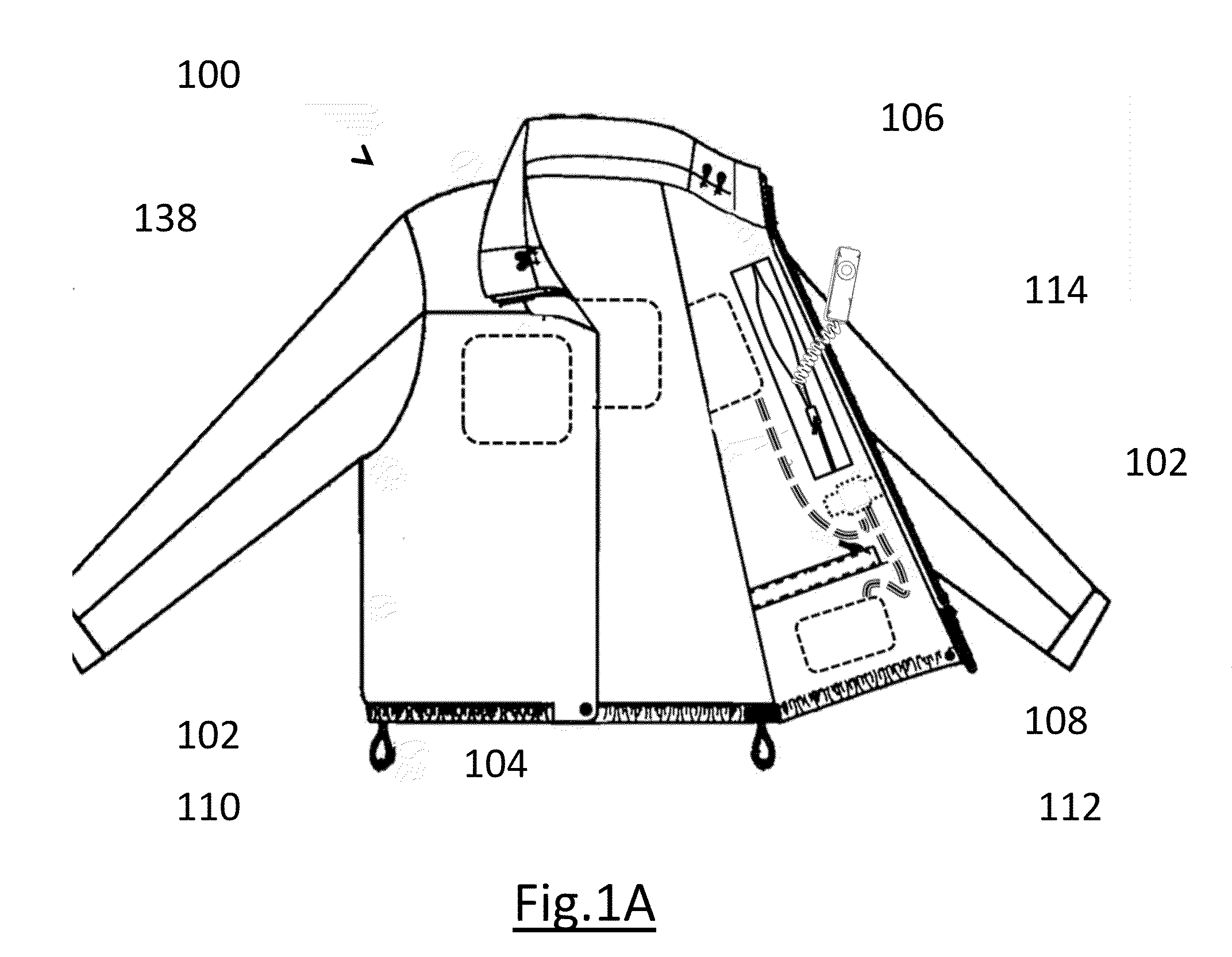
[0076]FIGS. 13 and 14 show a cross-sectional view of the garment 100 in accordance with the present invention shown in FIG. 1. Specifically, FIGS. 13 and 14 show a garment aperture region 1300 that has an inner fabric aperture 1308 creating an opening in fabric lining 1010 and an outer fabric aperture 1310 creating an opening in the garment inner fabric layer 1016 and the garment outer fabric layer 1004. Disposed within the inner fabric aperture 1308 is an inner cabling grommet 1302 having at least one resilient flap 1306. Disposed within the outer fabric aperture 1310 is an outer cabling grommet 1304 having at least one resilient flap 1306. The resilient flaps 1306 reduce airflow into and out of the garment to retain the insulating properties of the garment. As shown in FIG. 14, when an accessory cabling 1402 such as used for audio headphones is passed through grommets 1302 and 1310, the resilient flaps 1306 flex to allow passage of the accessory cabling but still retain their insu...
fourth embodiment
[0079]FIG. 16 is a schematic view of a wireless controller in accordance with the present invention of FIG. 1. It shows a wireless remote receiver controller 1602 which receives control signals from a wireless remote transmitter controller 1600 via radio frequency communication waves 1612. The wireless remote transmitter controller 1600 has a receiver housing 1604 made from a thermoplastic material. Disposed on the transmitter housing 1604 is a transmitter button 1608 and a transmitter indicator light 1610. The wireless remote receiver controller 1602 has a transmitter housing 1606 made from a thermoplastic material. Disposed on the receiver housing 1606 is a controller user operable switch 214 for local control and a controller indicator light 216 with functions as shown in FIG. 2. Disposed within the receiver housing 1606 is an antenna and radio frequency receiver circuitry (not shown) to receive the coded control signals from the wireless remote transmitter controller 1600 via ra...
PUM
 Abstract
Description
Claims
Application Information
 - R&D
- Intellectual Property
- Life Sciences
- Materials
- Tech Scout
- Unparalleled Data Quality
- Higher Quality Content
- 60% Fewer Hallucinations
Browse by: Latest US Patents, China's latest patents, Technical Efficacy Thesaurus, Application Domain, Technology Topic, Popular Technical Reports.
© 2025 PatSnap. All rights reserved.Legal|Privacy policy|Modern Slavery Act Transparency Statement|Sitemap|About US| Contact US: help@patsnap.com


