Ignition coil for internal combustion engine and method of making the same

a technology of ignition coil and internal combustion engine, which is applied in the direction of magnets, plastic/resin/waxes insulators, and magnets, etc., can solve the problems of difficult to employ resin compact of a contained amount of silica, insufficient resin compact between the lines of primary winding and secondary winding, etc., to reduce the development of electric trees, and improve the corona life.

Inactive Publication Date: 2009-11-26
DENSO CORP
View PDF9 Cites 15 Cited by
  • Summary
  • Abstract
  • Description
  • Claims
  • Application Information

AI Technical Summary

Benefits of technology

[0013]In the above manner, by sealing the primary coil and the secondary coil with the resin compact including silica in a range of 65 weight percent to 80 weight percent, particles of the filler which account for a weight fraction of a range of 65 percent to 80 percent in the resin compact serve as a significant block against development of an electric tree forming an insulation breakdown passage so as to limit the development of the electric tree, thereby improving a corona life.
[0014]Moreover, by composing a filler of 0 weight percent or more spherical silica and 40 weight percent or less crushed silica, variation in the corona life of the ignition coil is considerably improved and the ignition coil having a desired corona life is reliably obtained. It is well known that silica, which is generally included in the resin compact as a filler, is roughly divided between spherical silica and crushed silica based on their particle configurations.
[0015]By using the above-described resin compact, high voltage-resisting properties in proximity to the secondary coil, in which a corona discharge is particularly easily generated, are improved, so that an ignition coil having a long corona life is obtained.
[0016]For instance, a linear expansion coefficient of the resin compact is 10×10−6 to 27×10−6 / ° C. By using the resin compact having such a linear expansion coefficient, a difference between a linear expansion coefficient of a primary coil, a secondary coil and the like which constitute an ignition coil and the linear expansion coefficient of the resin compact becomes small. Accordingly, influence of a cold and hot cycle upon the ignition coil under the environment of its usage is mitigated. Thus, crack resistance of the resin compact improves, so that an ignition coil having a long corona life is obtained.

Problems solved by technology

However, in order to ensure a lifetime of such a high-output ignition coil against high withstand voltage, to obtain an insulation distance by increasing a size of the housing in a space above a plug hole or cylinder head to secure the high withstand voltage lifetime is not preferable from the standpoint of ensuring a space in a hood under the pedestrian protection law and the like.
However, as described above, when a contained amount of silica for the resin compact is 50 weight percent or above, viscosity of the resin compact increases, so that the resin compact is not sufficiently impregnated between the lines of the primary winding and secondary winding.
Therefore, in a high-output ignition coil, it has been difficult to employ the resin compact of a contained amount of silica being 50 weight percent or above.

Method used


Image

  • Ignition coil for internal combustion engine and method of making the same
  • Ignition coil for internal combustion engine and method of making the same
  • Ignition coil for internal combustion engine and method of making the same

Examples


Embodiment Construction

[0036]Embodiments of the present invention are described below with reference to drawings.

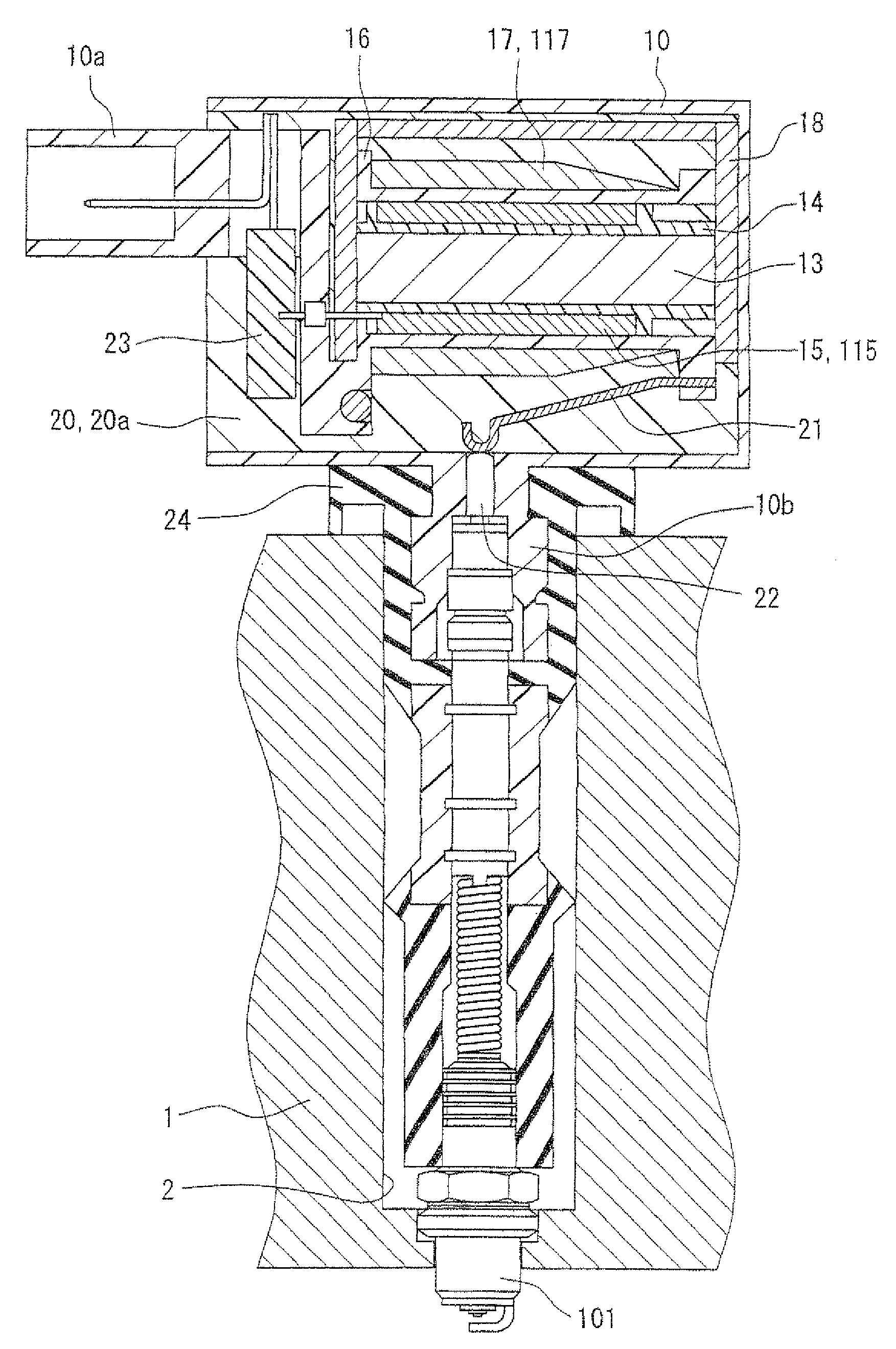
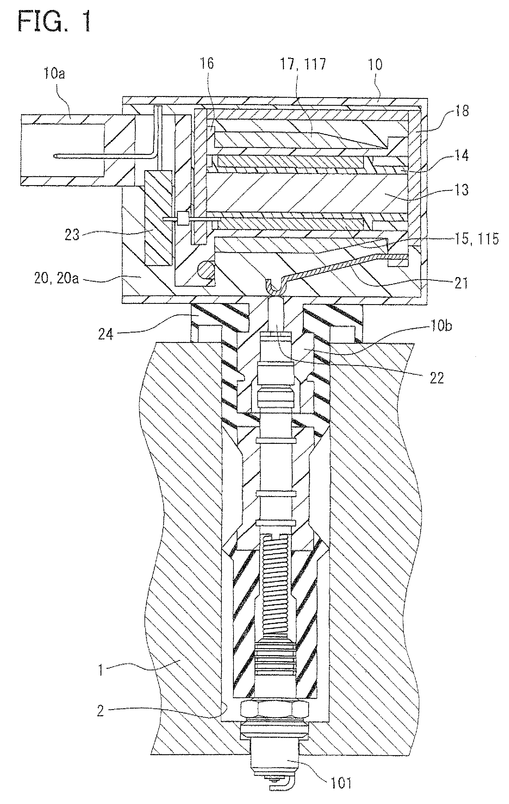
[0037]First, a basic constitution of an ignition coil 100 according to the present invention is explained. In addition, FIG. 1 is a schematic view of a longitudinal section of the ignition coil 100.

(Basic Constitution)

[0038]A housing 10 is made of hard resin such as PBT, and has a rectangular box shape having a larger bottom face than a cross-sectional area of a plug hole 2 of an engine head 1. The housing 10 is fixed to the outside of an opening of the plug hole 2. Furthermore, a connector part 10a projecting outward from the housing 10 is integrally formed respectively on a side wall of the housing 10. The connector part 10a serves to electrically connect an external power (not shown) and an igniter 23. Additionally, a cylindrical member 10b projecting from the housing 10 to the plug hole 2 side is integrally formed on a bottom wall of the housing 10 opposed to the engine head 1.

[0039]As show...


PUM

PropertyMeasurementUnit
diameteraaaaaaaaaa
weight percentaaaaaaaaaa

Abstract

An ignition coil for an internal combustion engine includes a primary coil formed by winding a primary winding a plurality of turns, a secondary coil formed by winding a secondary winding having a wire diameter of 30 to 100 μm a plurality of turns, and a resin compact which is impregnated into between the lines of the primary winding and between the lines of the secondary winding and which seals the primary coil and the secondary coil. The resin compact includes a filler in a range of 65 weight percent to 80 weight percent in order to limit development of an electric tree in the resin compact, and the filler is composed of 60 weight percent or more spherical silica and 40 weight percent or less crushed silica.

Description

CROSS REFERENCE TO RELATED APPLICATION[0001]This application is based on and incorporates herein by reference Japanese Patent Application No. 2008-106150 filed on Apr. 15, 2008 and Japanese Patent Application No. 2009-095458 filed on Apr. 10, 2009.BACKGROUND OF THE INVENTION[0002]1. Field of the Invention[0003]The present invention relates to an ignition coil for an internal combustion engine that generates a voltage applied to an ignition plug in the engine and a method of making the ignition coil.[0004]2. Description of Related Art[0005]An ignition coil for an internal combustion engine (hereafter referred to simply as a ‘ignition coil’) is for applying high voltage to an ignition plug attached to the engine so as to ignite fuel-air mixture, and is formed by sealing a primary coil, secondary coil, and the like with a resin compact made of thermosetting resin or the like (see, for example, JP-A-1 1-26267).[0006]Conventionally, as a method of sealing the primary coil and secondary c...

Claims


Application Information

Patent Timeline
Patent Type & Authority Applications(United States)
IPC IPC(8): H01F5/00H01F7/129
CPCH01B3/40H01F27/022H01F38/12H01F41/005Y10T29/49071Y10T29/4902
Inventor AKIMOTO, KATSUNORI
Owner DENSO CORP
Why Eureka
Try Eureka