
Folded conical antenna and associated methods

a conical antenna and antenna technology, applied in the field of antennas, can solve the problems of multiple tuning, insufficient bandwidth, and inability to meet all antenna size-bandwidth needs, and achieve the effect of wide voltage standing wave ratio (vswr) bandwidth

Inactive Publication Date: 2009-11-26
HARRIS CORP
View PDF14 Cites 15 Cited by
  • Summary
  • Abstract
  • Description
  • Claims
  • Application Information

AI Technical Summary

Benefits of technology

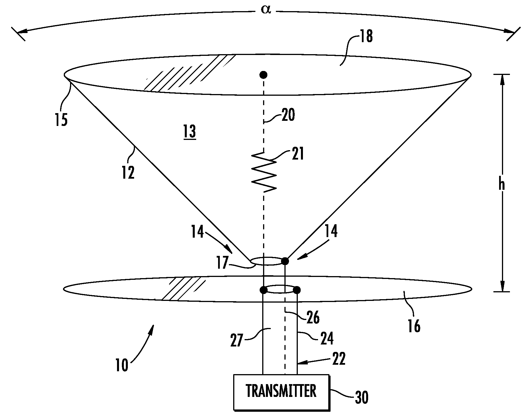
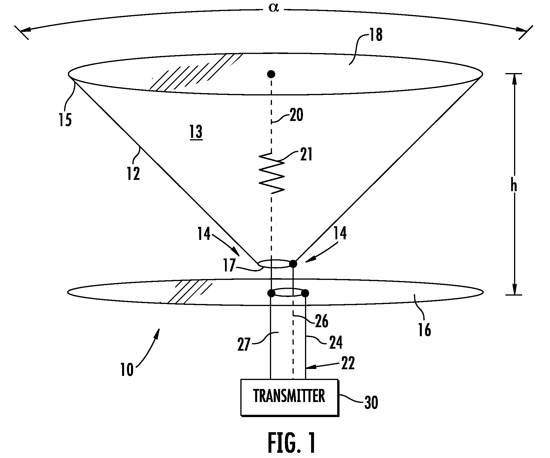
[0015]The approach may be referred to as a terminated discone antenna, or a resistor traded antenna which may include an impedance device such as a resistor and / or inductor placed at an electrical fold between the cone and the ground plane or disc. The fold conductor may be an internal wire providing a folded antenna circuit or folded conical monopole antenna, for example. The approach may include reduced gain above a cutoff frequency being traded for low VSWR below the cutoff frequency to get increased usable bandwidth.

Problems solved by technology

Jamming systems can use high power levels and the antenna must provide a low voltage standing wave ratio (VSWR) at all times. The bandwidth need may be instantaneous and tuning may not suffice.
Thus, in some systems it may be necessary to trade antenna gain for increased VSWR bandwidth by introducing losses or resistive loading.
Losses can be required when the antenna must operate beyond Chu's Limit, that is, to provide low VSWR at small and inadequate sizes.
Although beneficial, multiple tuning cannot be a remedy to all antenna size-bandwidth needs.
This is near 5 percent of Chu's single tuned gain bandwidth limit and it is often not adequate.
Yet, even conical antennas are not without limitation: the VSWR rises rapidly below the lower cutoff frequency.
Resistively terminated folded wire dipole antennas may have low VSWR but lack sufficient gain away from narrow resonances.
To obtain sufficiently low VSWR at low frequencies, they may be too physically large.
The large size may cause insufficient pattern beamwidth at the higher frequencies.

Method used


Image

  • Folded conical antenna and associated methods
  • Folded conical antenna and associated methods
  • Folded conical antenna and associated methods

Examples


Embodiment Construction

[0025]The present invention will now be described more fully hereinafter with reference to the accompanying drawings, in which preferred embodiments of the invention are shown. This invention may, however, be embodied in many different forms and should not be construed as limited to the embodiments set forth herein. Rather, these embodiments are provided so that this disclosure will be thorough and complete, and will fully convey the scope of the invention to those skilled in the art. Like numbers refer to like elements throughout.

[0026]Referring initially to FIG. 1, a conical monopole antenna 10 in accordance with features of the present invention will be described. The antenna 10 may be specified, for example, as a VHF / UHF omnidirectional conical monopole antenna operating between 100 to 512 MHz, and be usable to 30 MHz or below. The antenna 10 may be referred to as being an electrically small communication antenna with broad VSWR bandwidth. Also, the antenna may be referred to as...


PUM


Abstract

The conical monopole antenna includes a conical antenna element having an apex and a base, a conductive base member coupled across the base of the conical antenna element and a ground plane antenna element, e.g. a disc antenna element, adjacent the apex of the conical antenna element. A fold conductor is coupled between the conductive base member and the ground plane antenna element. The fold conductor may include at least one impedance element, such as a resistive element or inductive element. An antenna feed structure is coupled to the ground plane and conical antenna elements. The antenna may have reduced gain above a cutoff frequency being traded for low VSWR below the cutoff frequency to get increased usable bandwidth. The folded resistive termination is preferential to driving point attenuation and edge loading, and the conical monopole antenna provides low VSWR at most radio frequencies.

Description

FIELD OF THE INVENTION [0001]The present invention relates to the field of antennas, and more particularly, this invention relates to low-cost broadband antennas, conical and biconical antennas, folded antennas, omnidirectional antennas, and related methods.BACKGROUND OF THE INVENTION [0002]Modern communications systems are ever more increasing in bandwidth, causing greater needs for broadband antennas Some may require a decade of bandwidth, e.g. 100-1000 MHz. Various needs (e.g. military needs) may require broadband antennas for low probability of intercept (LPI) transmissions or communications jamming. Jamming systems can use high power levels and the antenna must provide a low voltage standing wave ratio (VSWR) at all times. The bandwidth need may be instantaneous and tuning may not suffice.[0003]In the current physics, instantaneous gain bandwidth is linked to antenna size through a relationship known as Chu's Limit (L. J. Chu, “Physical Limitations of Omni-Directional Antennas”...

Claims


Application Information

Patent Timeline
IPC IPC(8): H01Q13/00
CPCH01Q9/28H01Q9/40H01Q9/36
Inventor PARSCHE, FRANCIS EUGENE
Owner HARRIS CORP
Learn More