Liquid crystal apparatus, color filter substrate, and array substrate

a technology of liquid crystal apparatus and substrate, applied in non-linear optics, instruments, optics, etc., can solve the problems of difficult to coat the surface of the substrate with a polarizer material, difficult to obtain a polarizer having polarization characteristics that are uniform in a plane, and difficult to form a film uniformly on the surface, etc., to achieve excellent display characteristics, stable and stable results

Inactive Publication Date: 2009-11-26
SONY CORP
View PDF11 Cites 46 Cited by
  • Summary
  • Abstract
  • Description
  • Claims
  • Application Information

AI Technical Summary

Benefits of technology

[0023]In the embodiment, one polarization layer group is independently provided for each dot region or the plurality of dot regions. Accordingly, even in the array substrate used in the liquid crystal apparatus having a large screen such as a large-sized liquid crystal television, it is possible to divide the large screen and form the polarization layers for each divided region. Thus, the liquid crystal apparatus having the polarization characteristics that are uniform in a display surface thereof can be stably obtained. Specifically, when the liquid crystal apparatus is formed by coating an entire screen with polarization elements, it is extremely difficult to form a film uniformly on a surface in a large-sized substrate, and therefore a polarizer having polarization characteristics that are uniform in the surface can hardly be obtained. In contrast, according to the embodiment, one polarization layer group is independently disposed for each dot region and the plurality of dot regions, to thereby divide the entire surface of the su

Problems solved by technology

However, in a large-sized liquid crystal apparatus such as a liquid crystal television, it is difficult to coat a surface of a substrate with a polarizer material in a uniform thickness by the above-mentioned methods, and it is also difficult to obtain a polarizer having polarization characteristics that are uniform in a pla

Method used


Image

  • Liquid crystal apparatus, color filter substrate, and array substrate
  • Liquid crystal apparatus, color filter substrate, and array substrate
  • Liquid crystal apparatus, color filter substrate, and array substrate

Examples


first embodiment

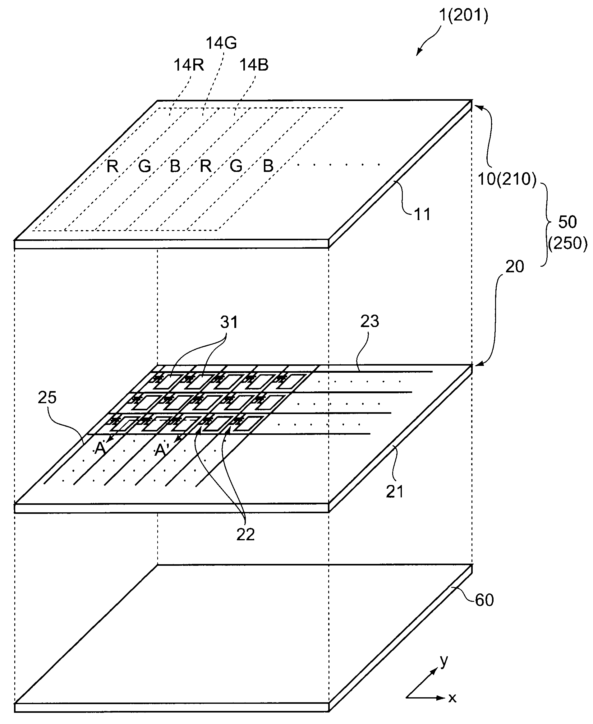
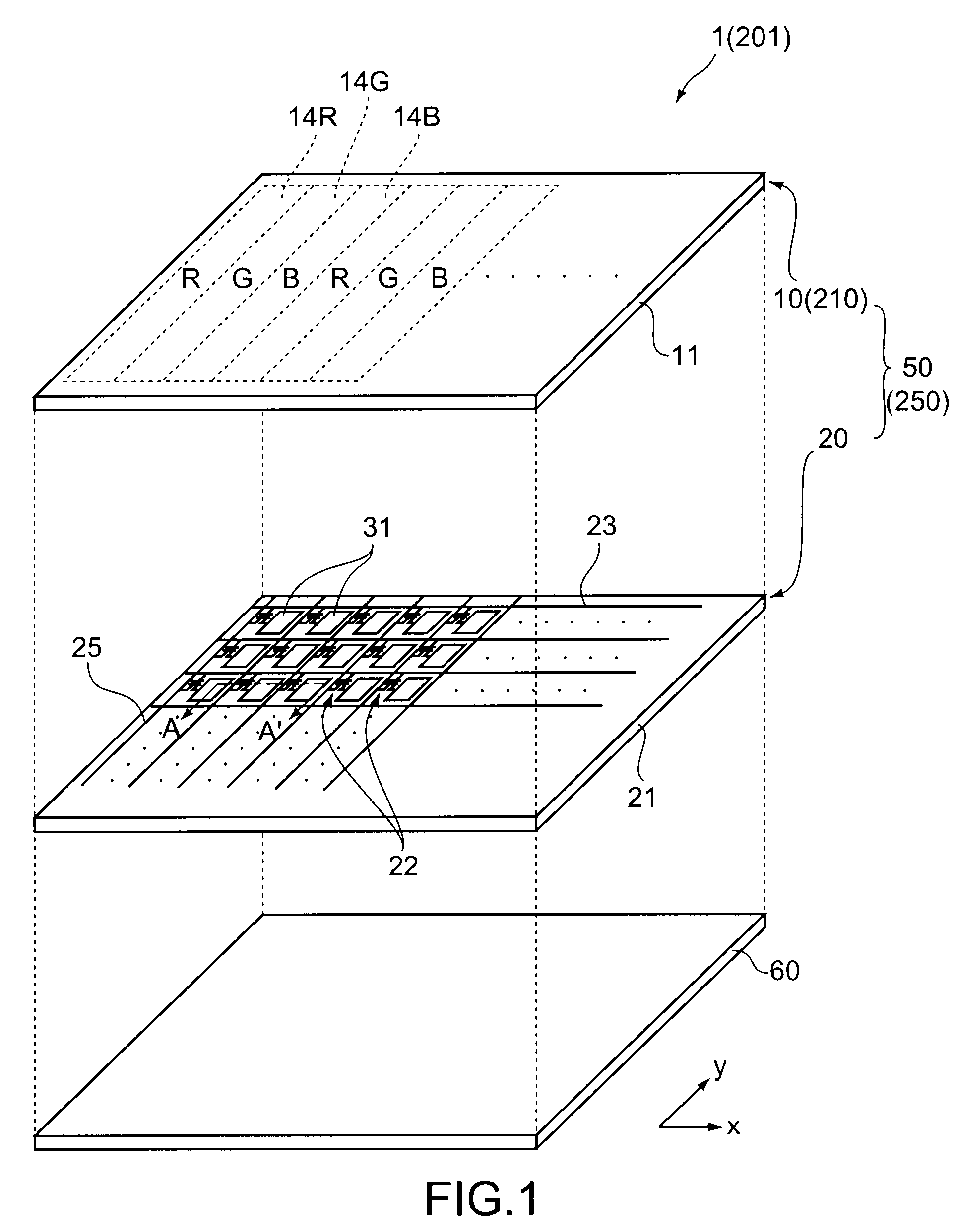
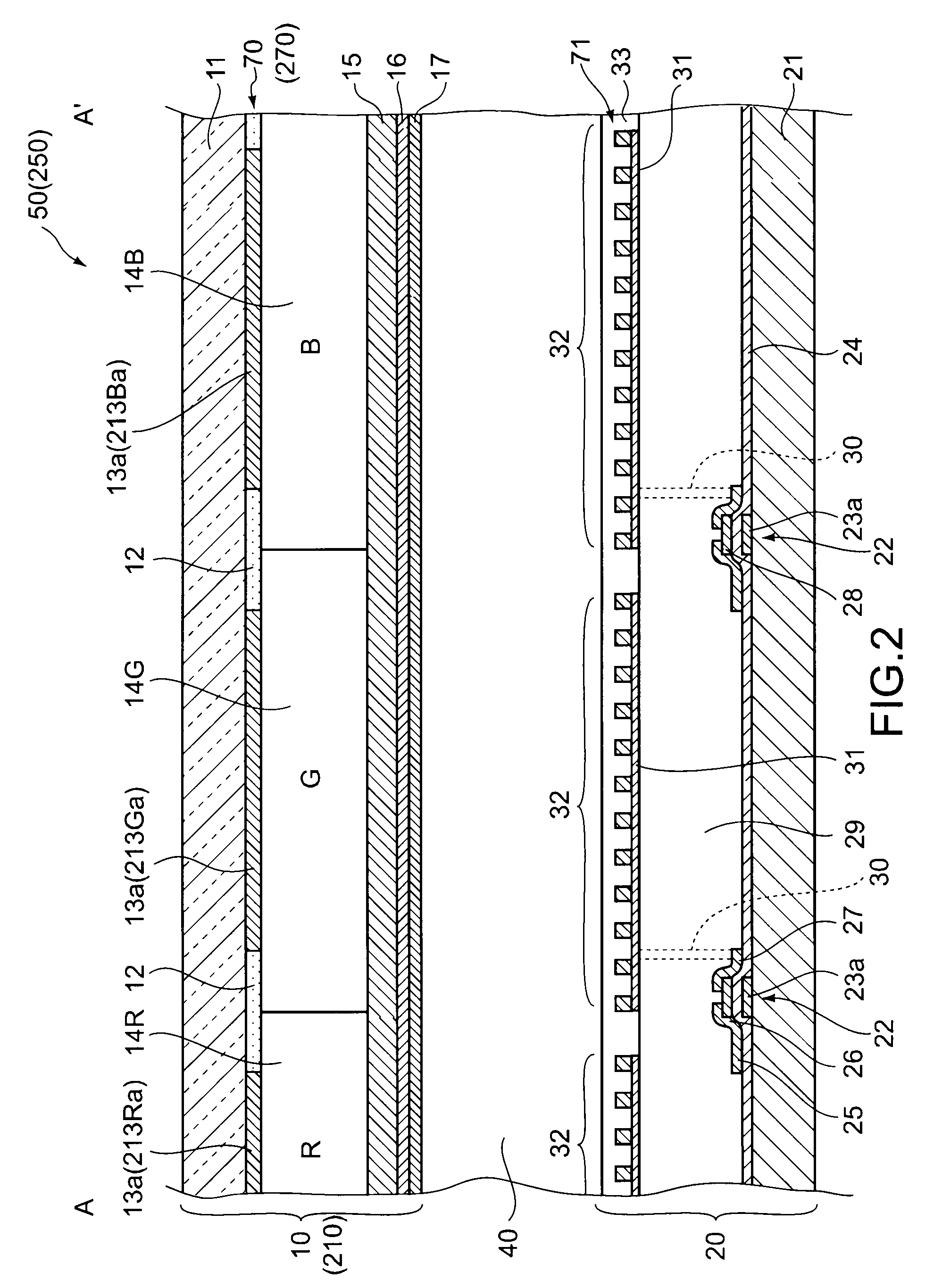
[0047]As an example, a transmissive color TFT (Thin Film Transistor) liquid crystal apparatus according to an embodiment of the present invention will be described with reference to FIGS. 1 to 5. To facilitate visualization of the drawings, the number of components is set to be different from that of a structure of an actual liquid crystal apparatus, and degrees of scaling down are set to be different between the components in the drawings.

[0048]FIG. 1 is an exploded perspective view schematically showing a liquid crystal apparatus, in which equivalent circuits are provided on an array substrate. FIG. 2 is a cross-sectional view of a liquid crystal cell 50 taken along the line A-A′ of FIG. 1. FIG. 3 is a partial schematic plan view showing a positional relationship among components formed on a color filter substrate 10 of the liquid crystal apparatus shown in FIG. 1. FIG. 4 is a partial schematic plan view showing a positional relationship among constituents formed on an array subst...

second embodiment

[0108]In the first embodiment, the materials of the inorganic fine particles used for the polarization layers corresponding to the dots of different colors of R, G, and B include the Ge component. In addition, it is also possible to change inorganic fine particles depending on the colors and provide the polarizer having polarization characteristics optimum for each color. Hereinafter, a description will be give with reference to FIGS. 1 to 4, 11, and 12. The same components as those in the first embodiment are denoted by the same symbols, and their descriptions are omitted. This embodiment is different from the first embodiment only in that the inorganic fine particle layer used for the polarization layer corresponding to each of the dots of R and G on the color filter substrate side contains the Ge component and the inorganic fine particle layer used for the polarization layer corresponding to the dot of B contains a Si (silicon) component.

[0109]FIG. 1 is an exploded perspective vi...

modified example

[0118]Hereinafter, a modified example will be described. The same components as those in the above embodiment are denoted by the same symbols and their descriptions are omitted.

[0119]In the above embodiments, the polarizer is disposed on the array substrate so that the longitudinal direction of the polarization layer is in parallel to the signal lines (y-axis direction), and on the color filter substrate, the polarizer having the polarization layer, the longitudinal direction of which is perpendicular to the longitudinal direction of the polarization layer of the polarizer disposed on the array substrate is disposed. In contrast, on the array substrate, the polarizer may be disposed on the array substrate so that the longitudinal direction of the polarization layer is in parallel to the scanning lines (x-axis direction), and on the color filter substrate, the polarizer having the polarization layer, the longitudinal direction of which is perpendicular to the longitudinal direction o...


PUM


Abstract

Disclosed is a liquid crystal apparatus including a plurality of dot regions. The liquid crystal apparatus includes a pair of transparent substrates disposed with a gap, a liquid crystal layer sandwiched by the pair of transparent substrates, and a polarizer formed by disposing, on at least one of surfaces of the pair of transparent substrates which are opposed to each other, a polarization layer group constituted of a plurality of polarization layers including an inorganic fine particle layer having a shape anisotropy, the polarization layer group corresponding to one of the dot region and the plurality of dot regions.

Description

BACKGROUND OF THE INVENTION [0001]1. Field of the Invention[0002]The present invention relates to a liquid crystal apparatus in which a polarizing plate function is implemented in a liquid crystal cell, and a color filter substrate and an array substrate that are used therefor.[0003]2. Description of the Related Art[0004]Generally, a liquid crystal apparatus is constituted of a liquid crystal cell and a pair of polarizing plates that are disposed therein. In the liquid crystal cell, a pair of electrode substrates sandwiches a liquid crystal layer. The pair of polarizing plates sandwiches the liquid crystal cell. For the polarizing plate, a dichroic polarizing plate obtained by causing a film in related art to contain an iodine or dye-based organic polymeric material is widely used.[0005]In contrast, in recent years, there has been studied a technique in which a polarizing plate function is implemented not outside but inside the liquid crystal cell in order to reduce a thickness and ...

Claims


Application Information

Patent Timeline
IPC IPC(8): G02F1/1335
CPCG02F1/133528G02F2001/133565G02F2001/133548G02F1/133548G02F1/133565
Inventor TAKADA, AKIO
Owner SONY CORP
Why Eureka
Try Eureka