
Automatic gain control apparatus and method in a wireless communication system

Active Publication Date: 2009-11-26
SAMSUNG ELECTRONICS CO LTD
View PDF12 Cites 52 Cited by
  • Summary
  • Abstract
  • Description
  • Claims
  • Application Information

AI Technical Summary

Benefits of technology

[0014]Still another aspect of the present invention provides an apparatus and method for adaptively adjusting a target RSSI for AGC to reduce performance degradation caused by an increase in quantization error when a reception signal from a transmitter and high-power interference signals (i.e. signals that a relay transmits to a receiver) are simultaneously received at a receiver of a full-duplex relay that performs interference cancellation.

Problems solved by technology

For these reasons, in the channel environment for wireless communication where high-power interference signals are received as a received signal, quantization error may increase as an AGC operation is performed on the entire received signal including the interference signals based on the fixed target RSSI.
The increase in quantization error causes performance degradation of the wireless communication system.

Method used


Image

  • Automatic gain control apparatus and method in a wireless communication system
  • Automatic gain control apparatus and method in a wireless communication system
  • Automatic gain control apparatus and method in a wireless communication system

Examples


first exemplary embodiment

A. First Exemplary Embodiment

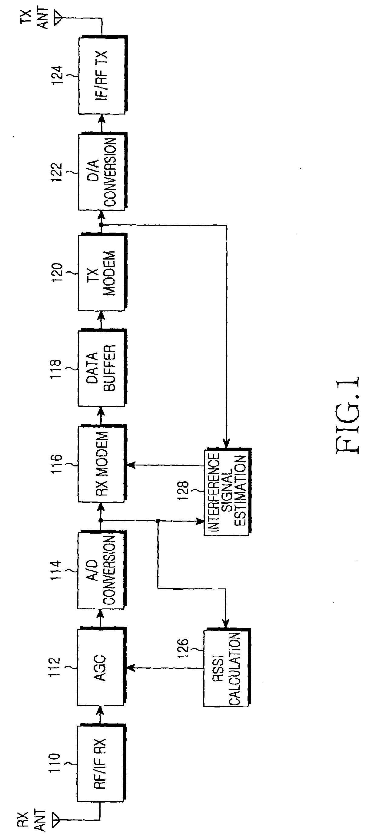
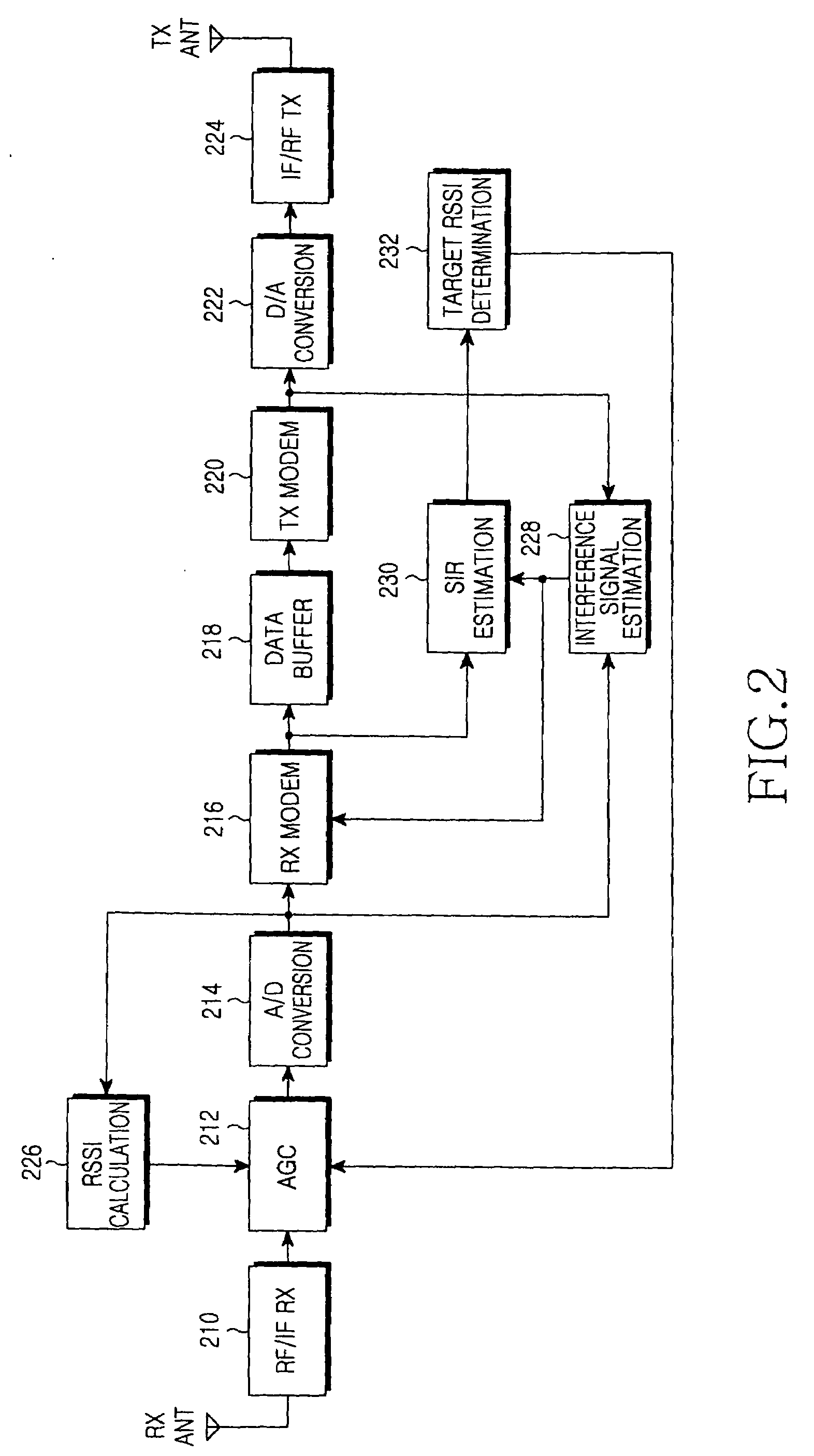
[0049]In a first exemplary embodiment of the present invention, an apparatus and method will be described in detail that estimates an interference signal and controls a gain for a received signal using a target RSSI determined based on the estimated interference signal. That is, a detailed description will be made of a structure for estimating an interference signal from a received signal, a structure for estimating an SIR based on the estimated interference signal, a structure for determining a target RSSI according to the estimated SIR, and a structure for adjusting a gain for the received signal based on the determined target RSSI.

[0050]FIG. 2 illustrates a structure of a full-duplex relay that sets a target RSSI for AGC according to a first exemplary embodiment of the present invention.

[0051]Referring to FIG. 2, an RF-band radio signal received via a receive antenna is provided to an RF / IF receiving block 210. The RF / IF receiving block 210 converts t...

second exemplary embodiment

B. Second Exemplary Embodiment

[0098]In a second exemplary embodiment of the present invention, an apparatus and method will be described in detail that determines a target RSSI by further considering an MCS level except the estimated interference signal, and adjusts a gain for a received signal using the determined target RSSI. For example, a structure of a new relay apparatus is proposed that further includes a structure for discriminating an MCS level in addition to the structure of the relay apparatus proposed in the first exemplary embodiment of the present invention.

[0099]A maximum-rate MCS level discrimination block that is further included in the second exemplary embodiment of the present invention, performs an operation of detecting a maximum-rate MCS level for each individual AGC unit using resource allocation information (e.g. MAP information) in order to determine a target RSSI.

[0100]The unit in which AGC is performed in the wireless communication system may be different ...


PUM


Abstract

An apparatus and method for adaptively adjusting a target Received Signal Strength Indicator (RSSI) for Automatic Gain Control (AGC) in a full-duplex relay apparatus with an interference cancellation function. A Signal to Interference Ratio (SIR) estimation block estimates an SIR based on an interference signal estimated from a received signal and an interference-cancelled signal determined by cancelling the estimated interference signal from the received signal. A target RSSI determination block determines a target RSSI according to the estimated SIR. An AGC block adjusts a gain for the received signal based on the determined target RSSI.

Description

CROSS-REFERENCE TO RELATED APPLICATION(S) AND CLAIM OF PRIORITY[0001]The present application claims the benefit under 35 U.S.C. §119(a) of a Korean Patent Application filed in the Korean Intellectual Property Office on May 23, 2008 and assigned Serial No. 10-2008-0048238, the entire disclosure of which is hereby incorporated by reference.TECHNICAL FIELD OF THE INVENTION[0002]The present invention relates to an Automatic Gain Control (AGC) apparatus and method in a wireless communication system. More particularly, the present invention relates to an apparatus and method for automatically controlling a gain taking interference signals into consideration.BACKGROUND OF THE INVENTION[0003]Commonly, electrical devices that process signals have an AGC circuit to reduce and prevent inter-modulation and saturation occurring in an amplification stage. In particular, an AGC circuit in a reception apparatus for a wireless communication system is used to obtain a signal having a desired level af...

Claims


Application Information

Patent Timeline
IPC IPC(8): H04B7/00
CPCH04B1/1027H03G3/3068H04B7/15535H04B1/59H04B7/14
Inventor HAN, SEUNG-HEEJUNG, SUNG-YOONYUN, SANG-BOHLEE, JOO-HYUN
Owner SAMSUNG ELECTRONICS CO LTD
Learn More