Calibrating radiofrequency paths of a phased-array antenna

a phased array and radiofrequency path technology, applied in the field of wireless communication systems, can solve the problems of not calibrating the rf cable, affecting the amplitude of the amplifier, and difficult to achieve a small beamwidth in a closely spaced antenna array,

Active Publication Date: 2009-11-26
ALCATEL LUCENT SAS
View PDF5 Cites 51 Cited by
  • Summary
  • Abstract
  • Description
  • Claims
  • Application Information

AI Technical Summary

Benefits of technology

[0007]In order to form a beam using closely spaced multiple antennas, calibration is required to equalize the amplitudes and phases among all antenna branches in the path between the radio and antenna. Angle of departure from the antenna array is determined by the phase difference between digital signals coming out of the radios. Calibration is usually performed digitally in the radios by using calibration signals to measure the amplitude and phase differences in the appropriate paths. The calibration coefficients or weights are then applied to the receive or transmit signals to compensate for the path differences. In the more common Frequency Division Duplex (

Problems solved by technology

Although a single antenna with a 65° beamwidth is commercially available, per antenna beamwidth this small is difficult to achieve in a closely spaced antenna array.
Second, this calibration method does not calibrate the RF cables to allow the base station to transmit fixed beamwidth common broadcast channels in boresight; the beamwidth is usually 65° in a three-sector

Method used


Image

  • Calibrating radiofrequency paths of a phased-array antenna
  • Calibrating radiofrequency paths of a phased-array antenna
  • Calibrating radiofrequency paths of a phased-array antenna

Examples


Embodiment Construction

[0019]Illustrative embodiments are described below. In the interest of clarity, not all features of an actual implementation are described in this specification. It will of course be appreciated that in the development of any such actual embodiment, numerous implementation-specific decisions should be made to achieve the developers' specific goals, such as compliance with system-related and business-related constraints, which will vary from one implementation to another. Moreover, it will be appreciated that such a development effort might be complex and time-consuming, but would nevertheless be a routine undertaking for those of ordinary skill in the art having the benefit of this disclosure.

[0020]The disclosed subject matter will now be described with reference to the attached figures. Various structures, systems and devices are schematically depicted in the drawings for purposes of explanation only and so as to not obscure the present invention with details that are well known to...


PUM


Abstract

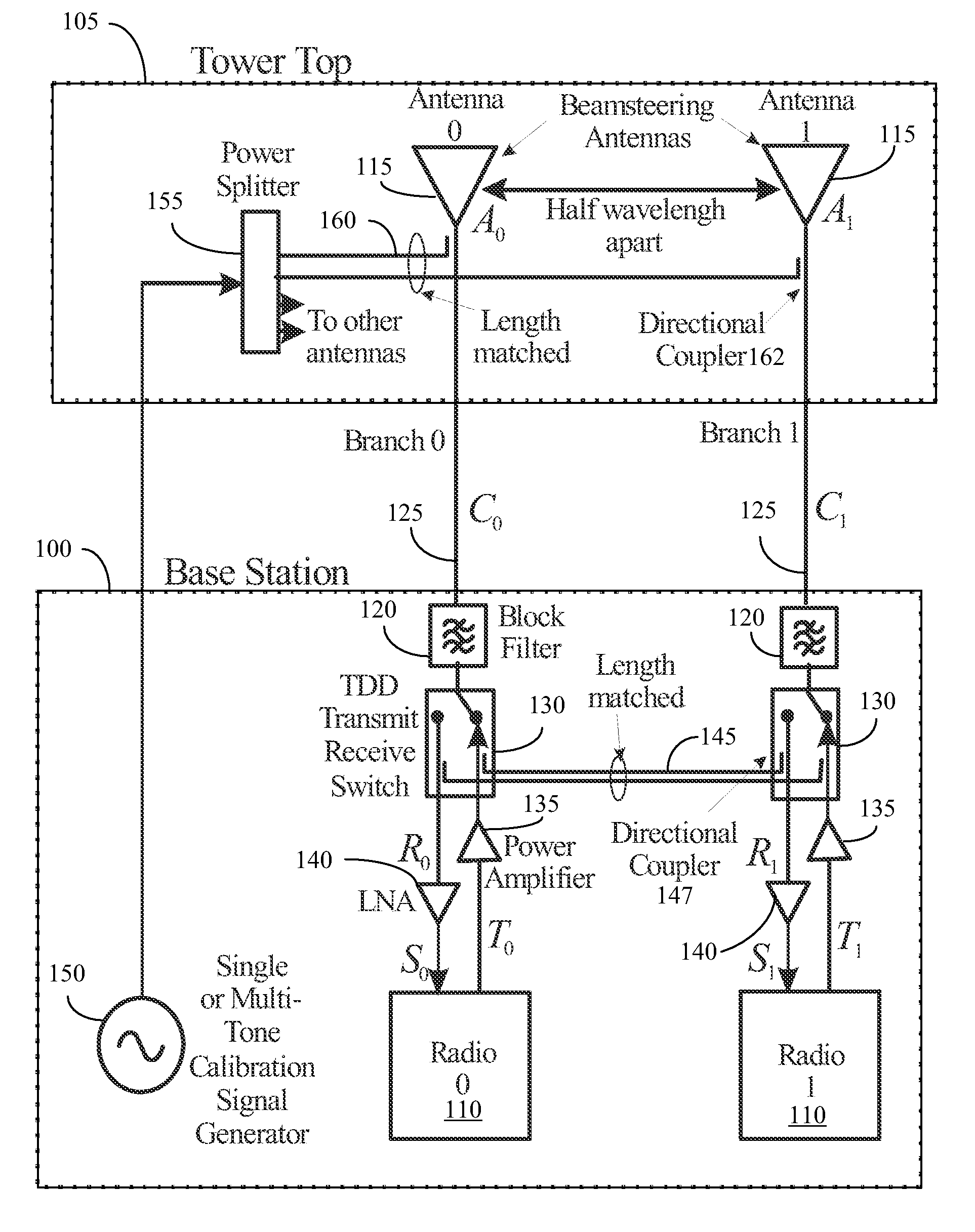
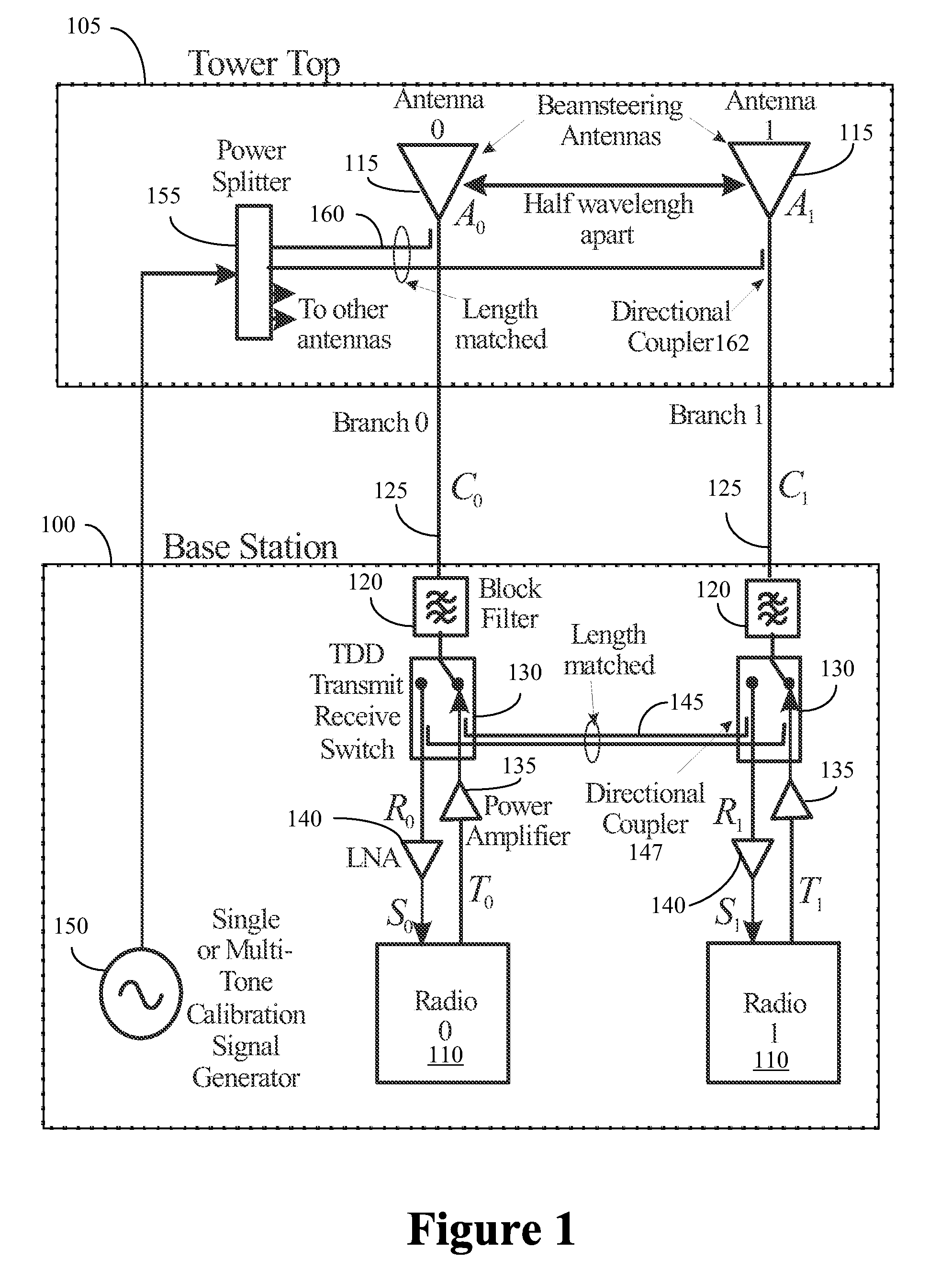
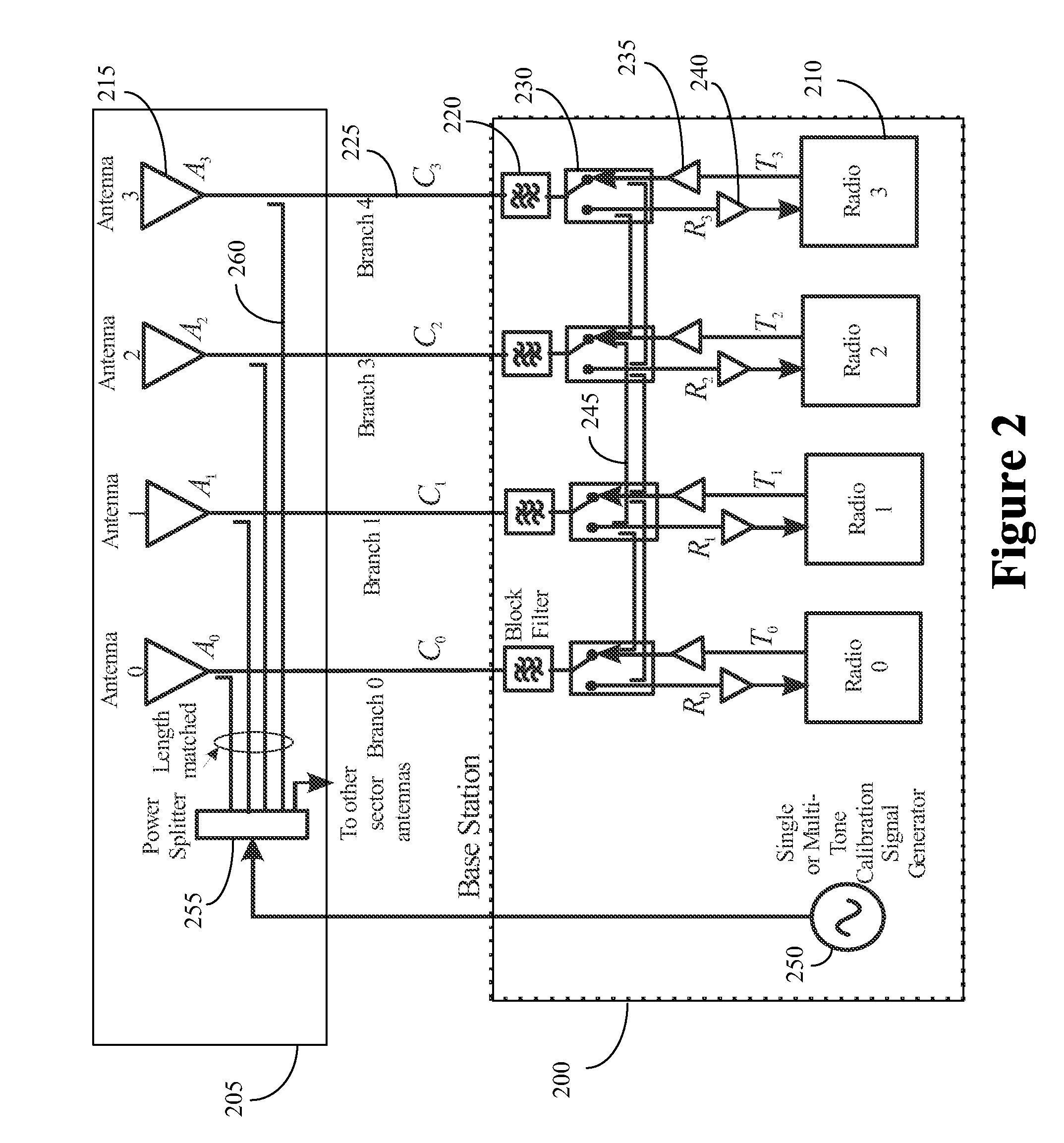
The present invention provides a method of calibrating base station comprising a plurality of antennas and operating in an Orthogonal Frequency Division Multiplex (OFDM) and Time Division Duplex (TDD) mode. One embodiment of the method includes a method of calibrating a base station comprising a plurality of antennas for beamsteering forward link traffic data to a target mobile in a TDD wireless communication system. Each antenna is connected to a corresponding radio via a transmit/receive switch that is configured to switch between a receive path and a transmit path. The method includes transmitting a first signal from a first radio via a first cross-over cable coupled to the first radio and a second radio such that the first signal is received by the second radio. The method also includes transmitting a second signal from the second radio via a second cross-over cable coupled between the first and second radios such that the second signal is received by the first radio. The method further includes determining, based on at least one of the first or second signals, a relative weight that can be applied to traffic signals transmitted from the second radio.

Description

BACKGROUND OF THE INVENTION[0001]1. Field of the Invention[0002]This invention relates generally to communication systems, and, more particularly, to wireless communication systems.[0003]2. Description of the Related Art[0004]Wireless communication systems typically include base stations that provide wireless connectivity to cover a geographical area such as a cell or a sector of a cell. The base stations communicate with mobile units in the cell or sector over an air interface. The air interface supports downlink (or forward link) communication from the base station to the mobile unit and uplink (or reverse link) communication from the mobile unit to the base station. The uplink and downlink communication uses corresponding uplink and downlink channels, which may be realized by use of carrier frequency, modulation, coding, frequency / time multiplexing, multiple antenna techniques, or combination thereof. Examples of standards and protocols that are used to define uplink and / or downl...

Claims


Application Information

Patent Timeline
IPC IPC(8): H04J3/00
CPCH01Q3/267H01Q21/0018H04B7/0617H04W28/16
Inventor RAO, SUDARSHAN A.WU, KAM HUNGYUAN, YIFEI
Owner ALCATEL LUCENT SAS
Why Eureka
Try Eureka