
Mode-locked external-cavity surface-emitting semiconductor laser

a semiconductor laser and surface-emitting technology, applied in the direction of laser optical resonator construction, laser details, active medium shape and construction, etc., can solve the problems of relatively bulky and expensive solid-state ultrafast lasers

Inactive Publication Date: 2009-11-26
COHERENT INC
View PDF8 Cites 37 Cited by
  • Summary
  • Abstract
  • Description
  • Claims
  • Application Information

AI Technical Summary

Problems solved by technology

Because of this, solid-state ultrafast lasers are relatively bulky and expensive.

Method used


Image

  • Mode-locked external-cavity surface-emitting semiconductor laser
  • Mode-locked external-cavity surface-emitting semiconductor laser
  • Mode-locked external-cavity surface-emitting semiconductor laser

Examples


Embodiment Construction

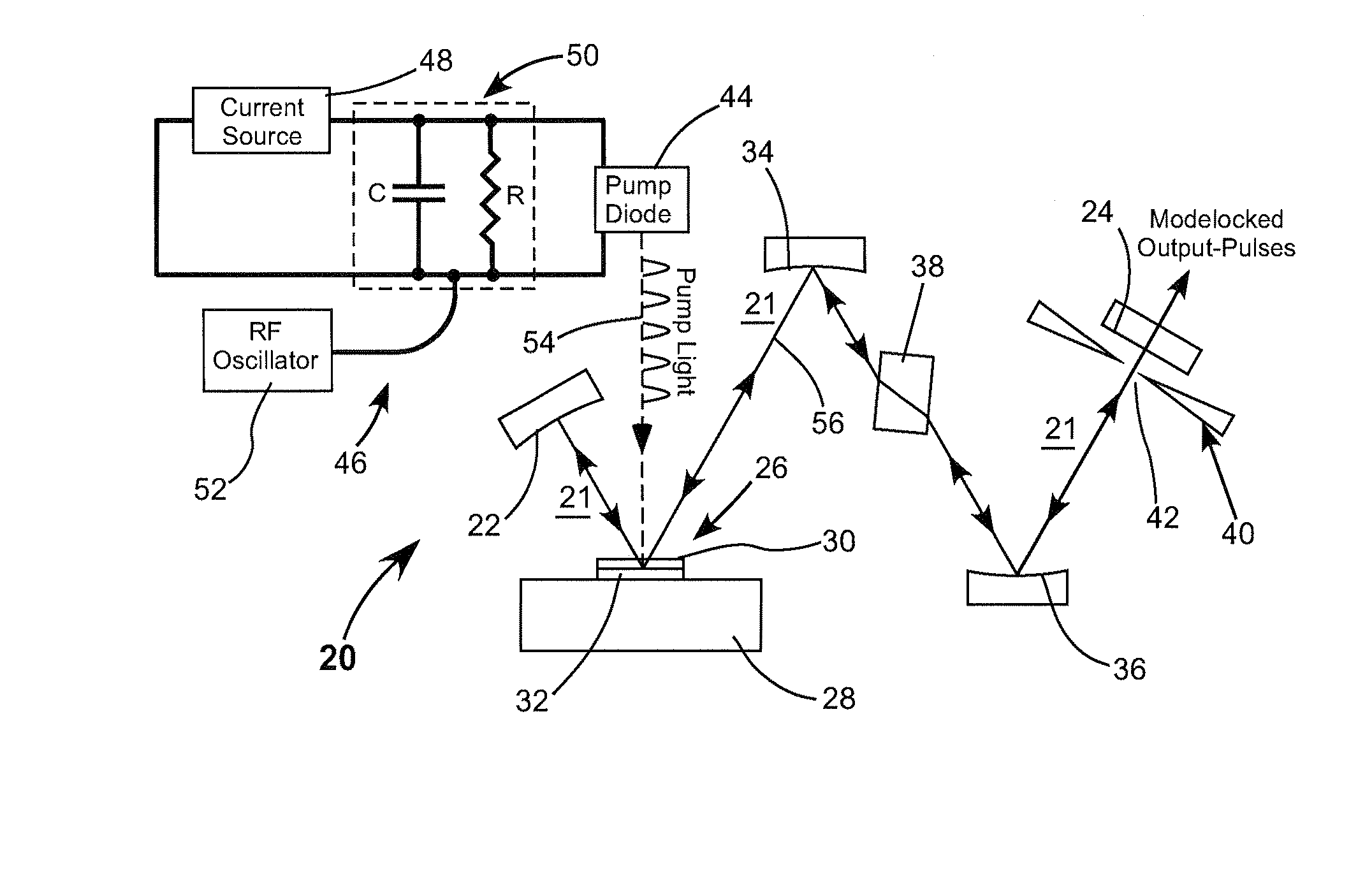
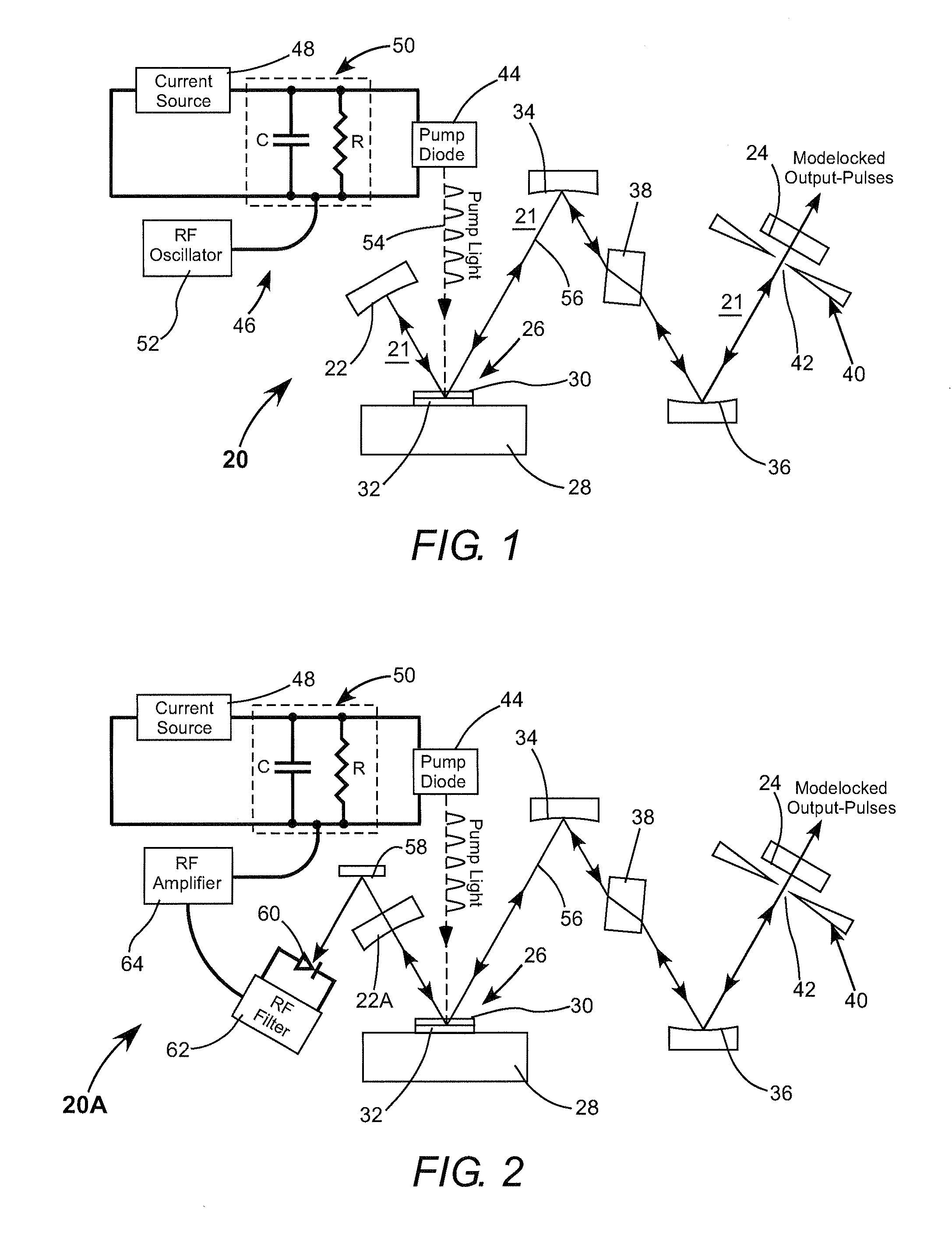
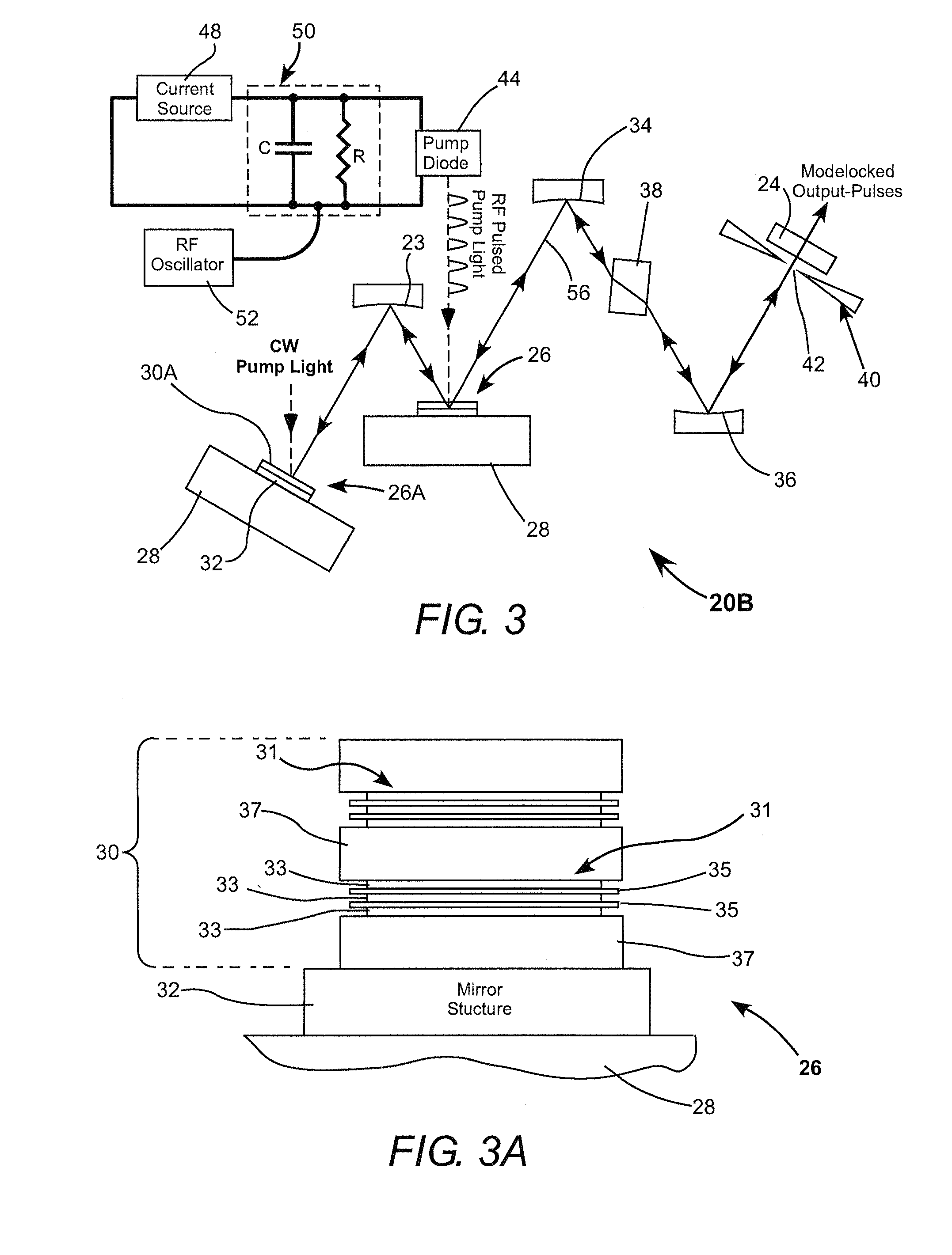
[0015]Referring now to the drawings, wherein like components are designated by like reference numerals, FIG. 1 schematically illustrates one preferred embodiment 20 of a mode-locked external-cavity surface-emitting semiconductor laser in accordance with the present invention. Laser 20 includes a laser-resonator 21 formed between mirrors 22 and 24. The resonator includes a multilayer, optically-pumped, semiconductor (OPS) structure (chip) 26 supported on a substrate or heat sink 28. OPS-structure 26 includes a multilayer gain-structure 30 including a plurality of quantum-well layers (not shown) spaced apart by spacer layers (not shown).

[0016]Gain-structure 30 surmounts a mirror-structure 32 which is arranged to be highly reflective at the fundamental wavelength. Mirror 22 is also highly reflective at this wavelength. Mirror 24 is partially reflective and partially transmissive at the fundamental wavelength and provides an outcoupling mirror of the resonator. It should be noted that o...


PUM


Abstract

A laser resonator includes an OPS gain-structure that is pumped with optical pulses repeatedly delivered at a pulse-repetition frequency corresponding to a resonant frequency of the laser resonator. The laser resonator additionally includes a passive mode-locking arrangement such that the resonator delivers mode-locked optical pulses. In one example the laser resonator further includes a CW optically pumped OPS gain-structure for increasing the power of the mode-locked pulses delivered from the resonator.

Description

TECHNICAL FIELD OF THE INVENTION[0001]The present invention relates in general to semiconductor lasers. The invention relates in particular to optically pumped semiconductor lasers configured to deliver ultra short pulses of radiation.DISCUSSION OF BACKGROUND ART[0002]Ultra short pulses of optical radiation from lasers configured to deliver such pulses are presently used in a variety of applications including microscopy, spectroscopy, laser surgery, and laser machining of inorganic materials. The term “ultra short” pulses as used here refers to pulses having a duration from about 100 picoseconds (ps) down to a few femtoseconds (fs).[0003]One commonly used laser for providing ultra short pulses is a laser having a solid-state gain-medium such as titanium-doped sapphire (Ti:sapphire), forsterite, alexandrite, or chrysoberyl. Ti:sapphire is usually preferred. Such materials have a broad gain-bandwidth in a spectral range between about 700 nanometers (nm) and 1000 nm. Certain types of s...

Claims


Application Information

Patent Timeline
IPC IPC(8): H01S3/098H01S3/10H01S3/091
CPCB82Y20/00H01S3/0604H01S3/07H01S3/094026H01S3/109H01S3/1022H01S3/1112H01S5/041H01S5/14H01S5/18358H01S5/3425H01S3/1109
Inventor CHILLA, JUAN L.RESAN, BOJANAUSTIN, R. RUSSEL
Owner COHERENT INC
Learn More