
Steam Generating Apparatus With Water-Cooled Solid State Switch

a technology of solid state switch and steam generating apparatus, which is applied in the direction of lighting and heating apparatus, application, and heating arrangement of immersion, etc., can solve the problems of system noise, significant temperature overshoot, and further disturbing sound

Active Publication Date: 2009-11-26
ALTMAN MITCHELL
View PDF6 Cites 10 Cited by
  • Summary
  • Abstract
  • Description
  • Claims
  • Application Information

AI Technical Summary

Benefits of technology

[0005]The steam generating system herein includes thermostatically controlled steam generating means for maintaining the steam bath environment at a desired temperature, means defining a water inlet path for conducting water from a water supply to the steam generating means, said inlet-defining means including an area of highly therma

Problems solved by technology

Such systems, however, typically resulted in significant temperature overshoots followed by a fall off in temperature to a point substantially below the desired temperature.
In addition to energy inefficiencies caused by such hysteresis, systems of this type suffered from noise created by the system.
This, in turn, would typically cause a further disturbing sound.
As steam baths moved out of commercial environments and into private homes, the noises and energy waste became increasingly undesirable.
The use of heat sinks and fans have not only added to the cost and size of the systems, but have frequently become a source of problems in themselves.
In addition to the potential for normal fan failures, the fans and switching devices of steam baths are typically mounted out of sight in dirty and / or dusty environments such as attics, basements and the like, where they are virtually never inspected or cleaned until there is a failure.
Heat sinks become less efficient as dirt accumulates on them, and fans become less reliable in such environments as well.

Method used


Image

  • Steam Generating Apparatus With Water-Cooled Solid State Switch
  • Steam Generating Apparatus With Water-Cooled Solid State Switch

Examples


Embodiment Construction

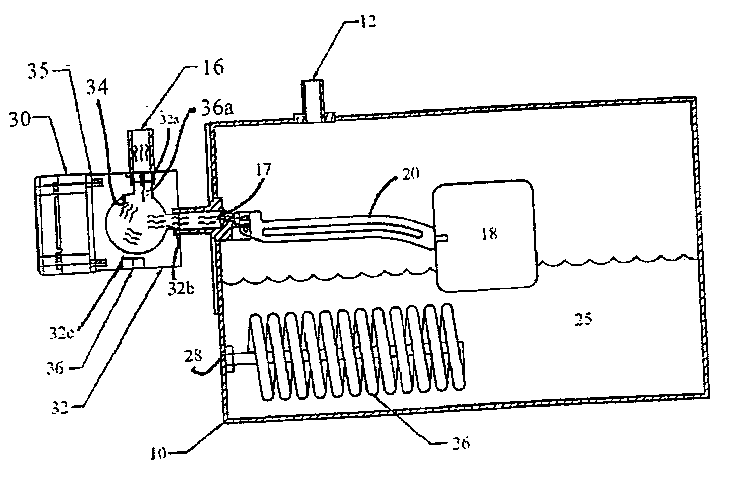
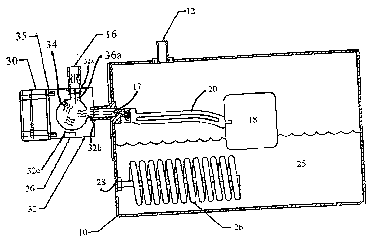
[0008]By way of example, the sole FIGURE herein FIG. 1 is a schematic view of a steam bath generator system constructed in accordance with the invention.

[0009]The steam generating system preferably comprises a stainless steel boiler tank 10 which can be of any convenient size and shape. The tank 10 has a steam outlet port 12, which is typically ½″ in diameter, as well as a water inlet port 16 through which water enters the tank via an external inlet nipple from an inlet pipe (not shown). A float 18, inserted into the tank through the inlet port 17, extends within the tank from a stem 20 is operatively connected to a flapper valve at the inlet port 17 to close the flapper when the level of water 25 in the tank reaches the maximum desired level, and to open the flapper when the water level is lower than the maximum desired level to permit the ingress of more water.

[0010]A heater coil 26 is inserted into the tank through a coil-receiving port 28 to heat the water to its boiling point a...


PUM


Abstract

A steam generating system for use in a steam bath includes thermostatically controlled steam generating means for maintaining the steam bath environment at a desired temperature, means defining a water inlet path for conducting water from a water supply to the steam generating means, said inlet-defining means including an area of highly thermally-conductive material in thermal contact with the water. The thermostatically controlled steam generating means includes an electrically powered heating element, and a solid state switching device for controlling the amount of electricity flowing in the heating element. The solid state switching device is in thermal contact with said highly thermally-conductive material so that the switching device is cooled via heat transfer to the water flowing in the inlet path.

Description

FIELD OF INVENTION[0001]This invention relates to steam generating apparatus for providing live steam to a shower or other enclosed area to create a steam room, and more particularly to the cooling of components of the steam generating apparatusBACKGROUND OF THE INVENTION[0002]Steam baths conventionally comprise a steam generator, a steam dispensing head and a thermostat responsive to the temperature of the steam bath environment to maintain a desired temperature by selectively activating and deactivating the generation of steam. Early steam bath systems used thermostats comprising electrical contactors that turned the steam fully on or completely off, as needed. Such systems, however, typically resulted in significant temperature overshoots followed by a fall off in temperature to a point substantially below the desired temperature. In addition to energy inefficiencies caused by such hysteresis, systems of this type suffered from noise created by the system. Upon activation, steam ...

Claims


Application Information

Patent Timeline
IPC IPC(8): H05B3/78
CPCA61H2201/5082A61H33/065
Inventor ALTMAN, MITCHELLSHARITZ, SCOTT
Owner ALTMAN MITCHELL
Learn More