Flow channel structure and method

a flow channel and flow channel technology, applied in the field of analytical chemical measurements, can solve the problems of difficult fluid connection with flow channel inputs, damage, and difficulty in achieving surface chemistry without damaging, and achieve the effect of maintaining a clean and reproducible biomoleculer interaction environmen

Inactive Publication Date: 2005-09-29
SENSATA TECHNOLOGIES INC
View PDF12 Cites 14 Cited by
  • Summary
  • Abstract
  • Description
  • Claims
  • Application Information

AI Technical Summary

Benefits of technology

[0031] This has advantages including: a flow channel block which does not deform or leach contaminating residues when assembled, thereby maintaining a clean and reproducible biomoleculer interaction environment. A reproducible seal defining a fixed flow channel volume is attained by simply pressing the hard flow channel block against a smooth, planar substrate such as an SPR sensor.

Problems solved by technology

Permanent attachment of a flow channel to the SPR active sensing region is possible but this is difficult to achieve without damaging the surface chemistry attached to the active sensing region.
Damage can occur due to chemical and / or mechanical damage during the flow channel attachment process.
In addition, making reliable, and reversible, fluid connections with the flow channel inputs is difficult.
Such delays decrease the reproducibility of binding responses from one SPR channel to the next and also make reference subtraction more difficult.
This integrated microfluidic cartridge is prone to clogging and needs to be replaced regularly.
In addition, silicone rubber is chemically inert and biocompatible.
Very little pressure is required to form a seal using flow channels formed in silicone rubber but the elasticity of silicone rubber also makes it difficult to hold tight tolerances on the flow channel dimensions.
This reference subtraction method will not be effective if the flow channel dimensions for each channel are significantly different (i.e., greater than 5% variation).
These design constraints add expense and / or technical difficulty to operating such SPR instruments.
In addition, they are slightly porous and may significantly absorb solution and biomolecules.
Therefore, flow channel heights below 15 μm are not practical for low pressure systems.
In addition, flow channels below this height are easily blocked by particulates that are often present in unfiltered samples and buffers.
In addition excess backpressure causes delays in reaching a steady-state flow.
Such delays have significant effects on the performance of the biosensor system.
If a bulk refractive index variation exists between the running buffer and sample, then the response due to this bulk index response is difficult to resolve from the actual binding signal, without using a reference channel, unless the exchange time can be reduced (i.e., to less than 10 seconds).
These velocity gradients cause uneven distribution of analyte binding at the surface.
Turbulent flow will exist at the inlet and outlet causing unpredictable analyte binding.
Known microfluidic systems have problems including a lack of reversible flow channel seals with inelastic materials.

Method used


Image

  • Flow channel structure and method
  • Flow channel structure and method
  • Flow channel structure and method

Examples


Embodiment Construction

[0035] 1. Overview

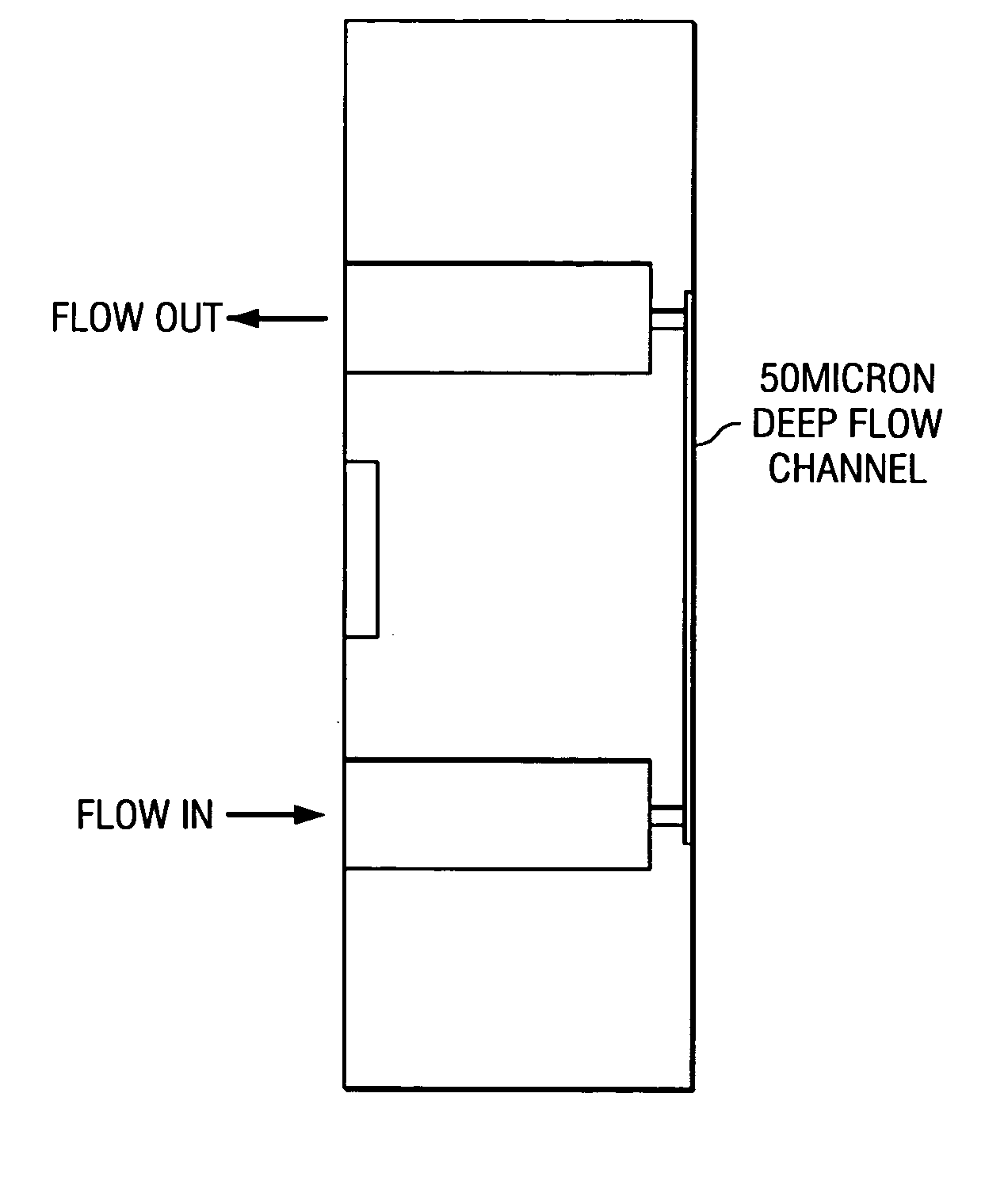
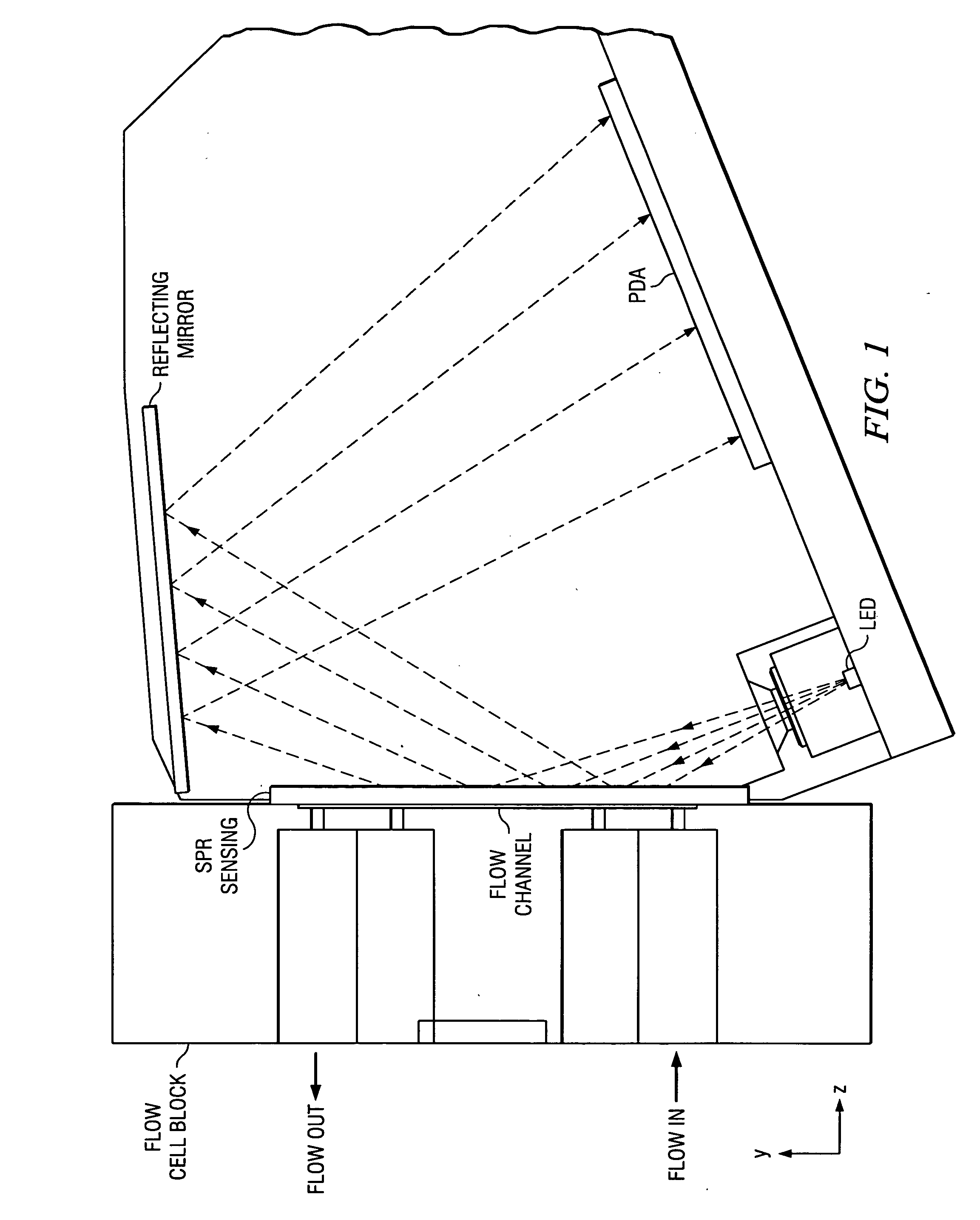
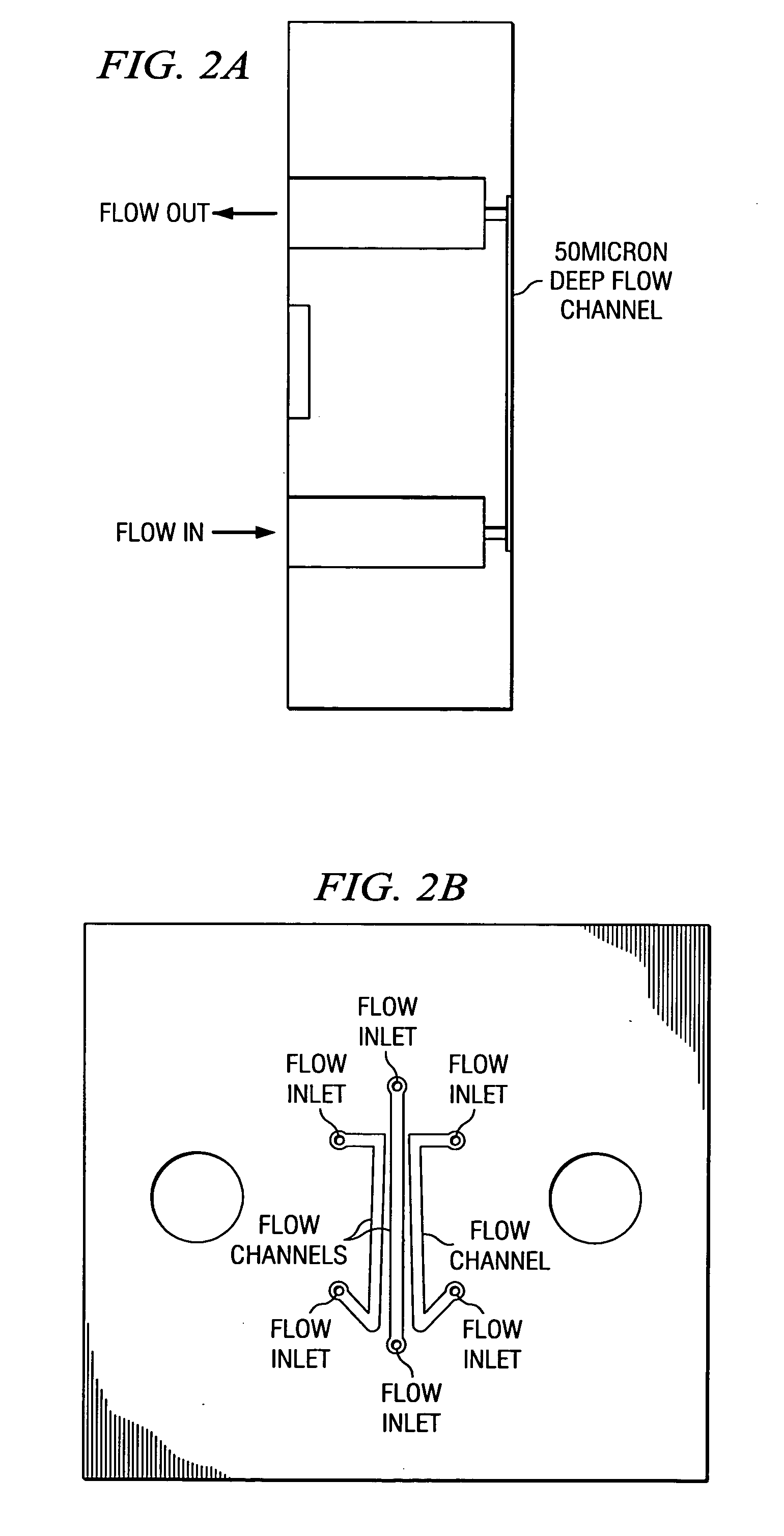
[0036] Preferred embodiment microfluidic devices have a flow channel block with a hard, smooth surface including recesses that define microfluidic flow channels. The recessed block surface is clamped to the sensor surface of a surface plasmon resonance (SPR) device to form a microfluidic channeled sensor system. The SPR sensing surface would typically be glass with a deposited thin (e.g., 50 nm thick) gold coating and an analyte-binding layer (e.g., 100-500 nm thick) bonded to the gold. FIG. 1 illustrates in cross sectional elevation view a preferred embodiment sensor system with the flow channel block in the left-hand portion of the Figure and the SPR sensor in the center and right-hand portion; FIGS. 2a-2b are side elevation and plan views of a preferred embodiment flow channel block which has three parallel flow channels. FIG. 2c is an engineering drawing showing a perspective view of this flow channel block.

[0037] Since there is no adhesive with the clamped p...


PUM

PropertyMeasurementUnit
surface roughnessaaaaaaaaaa
incident anglesaaaaaaaaaa
flatnessaaaaaaaaaa

Abstract

A microfluidic analysis system with a flow channel block, possessing at least one recessed channel, clamped to a sensor surface, such as a surface plasmon resonance (SPR) sensor. Flatness and hardness lead to a liquid leak-proof seal. Surface tension forces prevent liquid from leaking between the flow cell block and sensor surfaces. The fluid channels formed are reversible upon removal of the clamping pressure.

Description

BACKGROUND OF THE INVENTION [0001] The present invention relates to analytical chemical measurements, and more particularly to microfluidic devices and methods of manufacture and use. [0002] Analytical instruments such as biosensors are well established as a means of recording the progress of biomolecular interactions in real time. Biosensors are analytical instruments that employ a variety of transduction technologies in order to detect interactions between biomolecules. Such instrumentation requires microfluidic channels in order to deliver samples to a sensing region. Pumps and valves are prefered to provide a means of moving sample through the channels in a controlled reproducible manner. There are several transducers capable of recording the progress of biomolecular interactions, for example a quartz crystal microbalance. Binding of molecules to the surface of a quartz crystal changes the fundamental resonance frequency which allows quantitation of the binding event. Other tech...

Claims


Application Information

Patent Timeline
Patent Type & Authority Applications(United States)
IPC IPC(8): G01N1/10G01N21/05G01N21/27G01N21/55G01N33/543
CPCG01N21/05G01N21/274G01N2021/0346G01N33/54366G01N2021/058G01N21/553
Inventor QUINN, JOHN G.CARR, RICHARD A.
Owner SENSATA TECHNOLOGIES INC
Why Eureka
Try Eureka