Impeller of multiblade blower and method of manufacuturing the same

a multi-blade blower and blade technology, applied in the direction of non-positive displacement fluid engine components, liquid fuel engine components, circumferential flow pumps, etc., can solve the problems of increased manufacturing man-hours, low rotational strength, and increased manufacturing man-hours, so as to reduce the number of manufacturing man-hours, and reduce the variation of blade position accuracy

Inactive Publication Date: 2009-11-26
DAIKIN IND LTD
View PDF1 Cites 5 Cited by
  • Summary
  • Abstract
  • Description
  • Claims
  • Application Information

AI Technical Summary

Benefits of technology

[0008]When an impeller of a multiblade blower is manufactured by a resin, it is desirable to integrally mold by injection molding the circular support plates and the plurality of blades in order for there to be few variations in the positional accuracy of the blades, to improve rotational strength, and to reduce the number of manufacturing man-hours. However, due to restrictions of the molds and the like, it is difficult to form serrated shapes on the blades and injection-mold the blades and the circular support plates such that the blades and the circular support plates become integrated.
[0009]Thus, in this impeller of a multiblade blower, a step is formed in the blade face of each of the blades at a position a predetermined distance away from the blades tip where the serrated shape is formed, and injection molding-use molds that form this step are used, whereby it is possible to form the serrated shapes on the blade tips of the blades and mold the blades and the circular support plates such that the blades and the circular support plates become integrated. That is, according to the present invention, an impeller of a multiblade blower having a plurality of blades on whose blade tips are formed serrated shapes can be made into one where there are few variations in the positional accuracy of the blades and where rotational strength is improved, and the number of manufacturing man-hours can be reduced.

Problems solved by technology

However, the impeller of a multiblade blower having the above-described structure is manufactured by preparing the plurality of blades on whose blade tips are formed the serrated shapes and the circular support plates and then fixing the plurality of blades one blade at a time to the circular support plates, so there is the problem that variations in the positional accuracy of the blades occur when each of the blades is fixed to the circular support plates, and rotational strength is low.
Further, there is also the problem that the number of manufacturing man-hours increases.
Particularly when the impeller is manufactured by a resin, the number of manufacturing man-hours increases even more because it becomes necessary to use a solvent or an adhesive in order to reliably fix each of the blades to the circular support plates, and it is difficult to mass-produce the impeller.
However, due to restrictions of the molds and the like, it is difficult to form serrated shapes on the blades and injection-mold the blades and the circular support plates such that the blades and the circular support plates become integrated.

Method used


Image

  • Impeller of multiblade blower and method of manufacuturing the same
  • Impeller of multiblade blower and method of manufacuturing the same
  • Impeller of multiblade blower and method of manufacuturing the same

Examples


modification 1

(6) Modification 1

[0107]In the impeller 7 (that is, the first impeller-configuring body 13 and the second impeller-configuring bodies 14) of the preceding embodiment, the step 61 is formed in the rear blade face 51 of each of the blades 32 and 42, but as shown inFIG. 10 and FIG. 11, the step 61 may also be formed in the front blade face 52 of each of the blades 32 and 42. It will be noted that, because the shapes of the blades 32 and 42 are the same as those of the blades 32 and 42 in the preceding embodiment except that the step 61 is formed in the front blade face 52 (thus, the first blade face becomes 52a and the second blade face becomes 52b), description thereof will be omitted here.

[0108]In this case also, similar to the preceding embodiment, effects such as controlling turbulence in the airflow can be obtained.

[0109]Further, a method of manufacturing the impeller 7 (that is, the first impeller-configuring body 13 and the second impeller-configuring bodies 14) where the step 6...

modification 2

(7) Modification 2

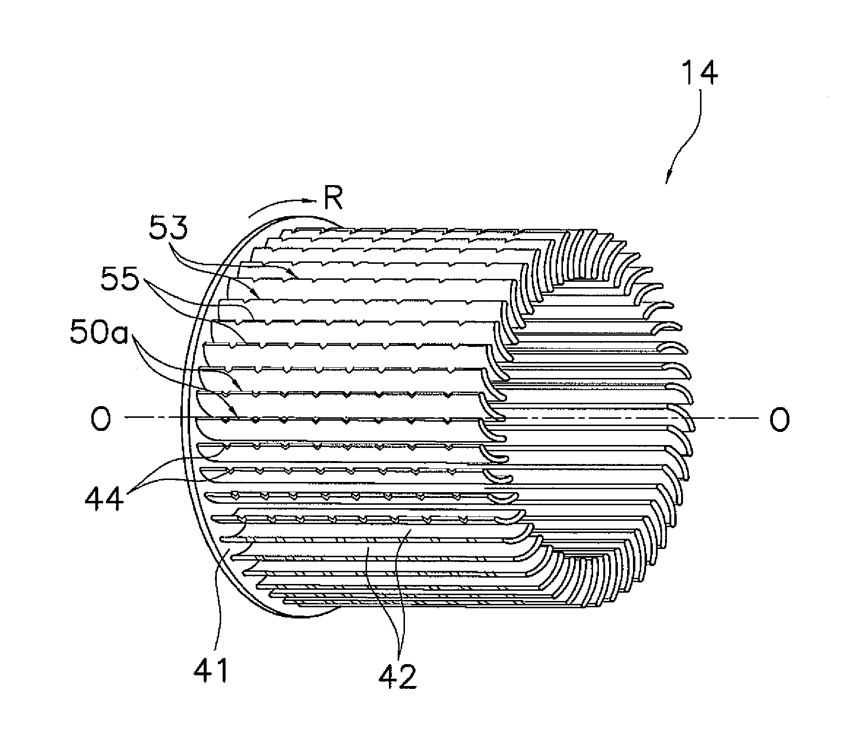
[0127]In the impeller 7 (that is, the first impeller-configuring body 13 and the second impeller-configuring bodies 14) of the preceding embodiment and modification 1, the serrated shape 53 is formed on the outer peripheral blade tip 50a of each of the blades 32 and 42, but the serrated shape 53 may also be formed on the inner peripheral blade tip 50b of each of the blades 32 and 42.

[0128]To describe this using the second impeller-configuring bodies 14 as an example, as shown in FIG. 15, the serrated shape 53 can be formed on the inner peripheral blade tip 50b of each of the blades 42.

[0129]When the second impeller-configuring body 14 is injection-molded, the outer peripheral portions of the blades 42 (specifically, the portions excluding portions to positions a predetermined distance (e.g., the distance σ) from the inner peripheral blade tips 50b of the blades 42) are formed by the second axial-direction-removable mold 181, and the radial-direction-removable molds...

modification 3

(8) Modification 3

[0136]In the impeller 7 (that is, the first impeller-configuring body 13 and the second impeller-configuring bodies 14) of the preceding embodiment and modifications 1 and 2, the cutout portions 54 and the smooth portions 55 configuring the serrated shapes 53 formed on the blade tips of the blades 32 and 42 were alternately disposed in the longitudinal direction of the blades 32 and 42, but as shown in FIG. 17, for example, the serrated shapes 53 may also have a structure comprising just the cutout portions 54 (that is, such that the serrated shapes do not include the smooth portions 55 between the cutout portions 54 in the longitudinal direction).

(9) Other Embodiments

[0137]Embodiments of the present invention have been described above on the basis of the drawings, but the specific configuration thereof is not limited to these embodiments and is alterable in a range that does not depart from the gist of the invention.


PUM

PropertyMeasurementUnit
thicknessaaaaaaaaaa
sizeaaaaaaaaaa
of rotationaaaaaaaaaa

Abstract

An impeller of a blower is disposed with circular support plates that are made of a resin and rotate about an axis of rotation and a plurality of blades that are made of a resin. The blades are disposed on outer peripheral portions of the circular support plates so as to be parallel to an axis of rotation, and serrated shapes are formed on the blades by cutting out blade tips at plural places. Additionally, a step is formed in a blade face of each of the blades at a position a predetermined distance from the blade tip where the serrated shape is formed.

Description

TECHNICAL FIELD[0001]The present invention relates to an impeller of a multiblade blower and a method of manufacturing the same.BACKGROUND ART[0002]Conventionally, there has been an impeller of a multiblade blower where a plurality of blades are disposed on outer peripheral portions of circular support plates so as to be parallel to an axis of rotation of the circular support plates. In such an impeller of a multiblade blower, oftentimes noise that arises due to an airflow passing through the blades configuring the impeller becomes a problem.[0003]In order to reduce such noise, an impeller structure has been proposed where serrated shapes are formed on blade tips of the blades configuring the impeller to thereby prevent separation of the airflow on negative pressure surfaces of the blades, reduce vortexes that occur on the rear edges of the blades, and reduce noise (see Patent Document 1).[0004]<Patent Document 1> JP-A No. 11-141494DISCLOSURE OF THE INVENTION[0005]However, the...

Claims


Application Information

Patent Timeline
Patent Type & Authority Applications(United States)
IPC IPC(8): F04D29/26B28B1/24
CPCF04D17/04F04D29/283Y10S416/02F04D29/626F04D29/30F05D2240/304F04D29/663F04D25/08F05D2240/30
Inventor HARAGUCHI, KAZUYAKAGAWA, YOSHINORITANAKA, HIDESHIYOSHINAGA, KOUZOU
Owner DAIKIN IND LTD
Why Eureka
Try Eureka