Dispersion lance and shield for dispersing a treating agent into a fluid stream

a technology of dispersion lance and shield, which is applied in the direction of transportation and packaging, other chemical processes, separation processes, etc., can solve the problem that the overall distribution of the surface area of the injected treating agent (such as the exemplary sorbent) is not markedly uniform along the length of the lance, so as to improve the overall distribution of the injected medium, improve the overall distribution of the surface area, and improve the utilization of the injected sorbent

Active Publication Date: 2009-12-03
URS
View PDF23 Cites 17 Cited by
  • Summary
  • Abstract
  • Description
  • Claims
  • Application Information

AI Technical Summary

Benefits of technology

[0009]To address this issue, we have now developed a multi-pipe lance, where each pipe supplies a minimum of feed discharge nozzles (typically one to four), and the individual pipes branch off from the same location or are otherwise fed with the sorbent or other treating agent to be dispersed. We have found that use of the multi-pipe lance in combination with a suitable baffle, results in better overall dispersion/distribution of the injected medium by surface area. By improving the surface area distribution, better utilization of the injected sorbent can be achieved
[0010]The multi-pipe lance retains the bulk, in-duct mixing properties of the '654 lance, and improves the distribution of surface area of the injected sorbent along the length of the lance. The improved surface area distribution is accomplished through the use of a dispersion lance mounted in the gas-carrying duct with its axis approximately transverse to the direction of the fluid stream flow, the lance having a treating agent feed section, and a plurality of parallel pipes extending from said section, each said pipe having one or more feed discharge nozzles along its length for injecting the treating agent supplied to said pipe into the fluid stream. A baffle extends lengthwise along the upstream side of the lance, the baffle preferably being formed as a partial cylindrical surface, such as the surface of a semi-cylinder. The convex side of the cylindrical surface faces upstream of the fluid stream flow, and adjoins generally flattened wing portions which extend from the lateral edges of the cylindrical surface to beyond the lateral sides of the multiple pipes, where the wings transversely intersect the stream flow. The baffle acts to generate a low pressure zone on the downstream sides of the nozzle-feed pipes, which enhances turbulence in the gas. The feed discharge nozzles of the nozzle-feed pipes are located to inject the treating agent into the low pressure zone to better distribute and intermix the injected treating

Problems solved by technology

Although the lance construction in our '654 application results in much improved mixing relative to the prior art lance, the overall distribution of the surface area of the injected treating agent (such as the exemplary sorbent) was found to not be markedly unifor

Method used


Image

  • Dispersion lance and shield for dispersing a treating agent into a fluid stream
  • Dispersion lance and shield for dispersing a treating agent into a fluid stream
  • Dispersion lance and shield for dispersing a treating agent into a fluid stream

Examples


Embodiment Construction

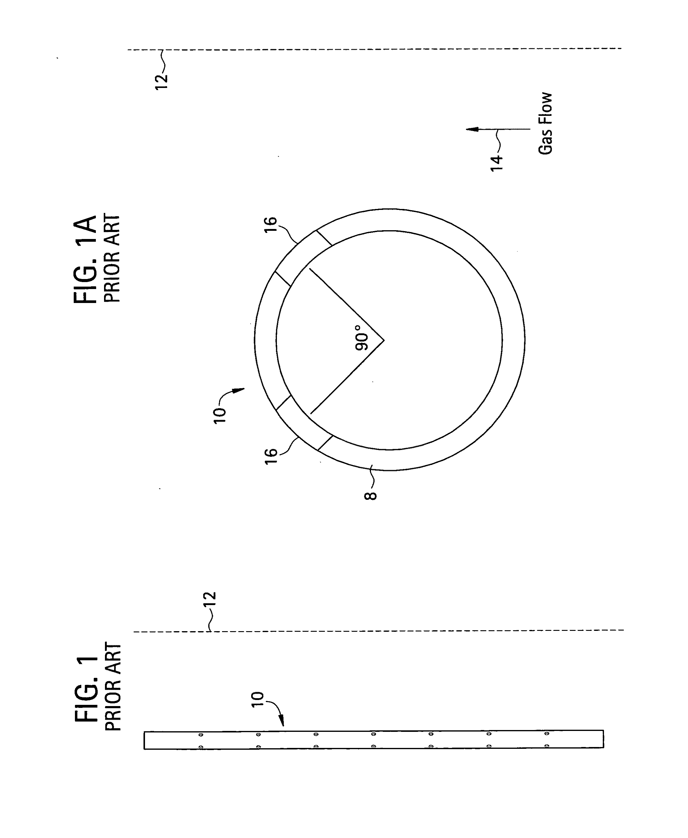
[0030]In FIGS. 1 and 1A schematic transverse and plan sectional views of a typical prior art dispersion lance 10, which is positioned in a duct 12 carrying a gas stream flow 14 which is being treated with a particulate ejected from the lance. The position of the lance within duct 12 is not shown to scale; rather the duct 12 and its actual wall spacing from lance 10 is merely intended to be suggested by the dotted lines used here—and as well in FIG. 2A. Also while dimensions and certain angles are shown in FIGS. 1, 1A, 2 and 2A, these are cited for illustration only and are not in any way intended to be limiting of the invention. The lance 10 comprises a pipe 8 which is mounted in duct 12 by means not shown. Pipe 8 has two parallel lines of openings 16 along its length. As seen in FIG. 1A the parallel lines of openings 16 are at the downstream facing side of pipe 8, and are oriented so that axial openings in opposed lines are at an angle of about 90° with respect to each other. The p...


PUM

PropertyMeasurementUnit
Fractionaaaaaaaaaa
Fractionaaaaaaaaaa
Lengthaaaaaaaaaa

Abstract

A dispersion apparatus for dispersing a treating agent into a fluid treatment system that includes a flow duct in which a fluid stream flowing through the duct is mixed with the treating agent. The apparatus is based on a multi-pipe lance positioned in the stream flow, where each pipe supplies a minimum of feed discharge nozzles (typically one to four), and the individual pipes branch off from the same location. Use of the multi-pipe lance, in combination with a suitable baffle, results in better overall dispersion/distribution of the injected medium by surface area. By improving the surface area distribution, better utilization of the injected sorbent can be achieved. The baffle acts to generate a low pressure zone on its downstream side and creates a high-intensity turbulence plume in the fluid. The orifices of the pipe are located to inject the treating agent into the turbulence plume to better distribute and intermix the injected treating agent into the surrounding fluid.

Description

RELATED APPLICATION[0001]This application is a continuation-in-part of U.S. patent application Ser. No. 12 / 152,654, filed May 15, 2008. The latter claimed priority from U.S. Provisional Patent Application No. 60 / 930,703 filed May 18, 2007.FIELD OF INVENTION[0002]This invention relates generally to apparatus and methods for fluid treatment, and more specifically relates to apparatus for injecting a treating agent into a fluid stream while generating enhanced fluid phase turbulence to better distribute and intermix the injected treating agent into the surrounding fluid.BACKGROUND OF INVENTION[0003]During the course of treating an acid or other gas, in order for example to control the atmospheric emission of polluting contaminants such as sulfur oxides, it is common as one step of the process to disperse solid particles of a treating agent such as a carbonate into the gas in order to react with or adsorb the undesired component. In order to do this a dispersion lance or other device or...

Claims


Application Information

Patent Timeline
IPC IPC(8): B01D53/06B01D15/00B01J19/00
CPCB01D53/79B01D53/83B01F3/06B01F5/0451B05B7/0075B01F5/0456B01F5/0463B01F5/0616B05B1/20B01F5/0453B01F23/30B01F25/31322B01F25/3131B01F25/3132B01F25/31331B01F25/4315
Inventor MILLER, SCOTT D.DENLINGER, MARK A.
Owner URS
Why Eureka
Try Eureka