Press and method for laminating essentially plate-shaped workpieces

Inactive Publication Date: 2009-12-03
ROBERT BURKE GMBH
View PDF2 Cites 3 Cited by
  • Summary
  • Abstract
  • Description
  • Claims
  • Application Information

AI Technical Summary

Benefits of technology

[0017]Here it is especially advantageous if the membrane frame could be attached to the upper press half utilizing quick-release closures. Such quick-release closures could then be operated advantageously by operating personnel even when the press is at the operating temperature, so that the cooling and heating cycles for replacing a defective membrane could be eliminated.
[0018]Special advantages are given when the membrane frame is divided into an upper membrane frame half and a lower membrane frame half between which the membrane is tensioned. In this way, the handling of the membrane frame with the tensioned membrane is simplified, because the membrane is better protected by its “internal” arrangement.
[0019]In particular, for such a two-part construction of the membrane frame, this could be provided on the upper side and lower side with seals and could form the sealing frame for forming the vacuum chamber between two otherwise flat press halves—these could be individual heating plates of a multi-s

Problems solved by technology

In this way, the time required for replacing a membrane that has become defective is limited to the removal of the membrane frame together with the

Method used


Image

  • Press and method for laminating essentially plate-shaped workpieces
  • Press and method for laminating essentially plate-shaped workpieces
  • Press and method for laminating essentially plate-shaped workpieces

Examples


Example

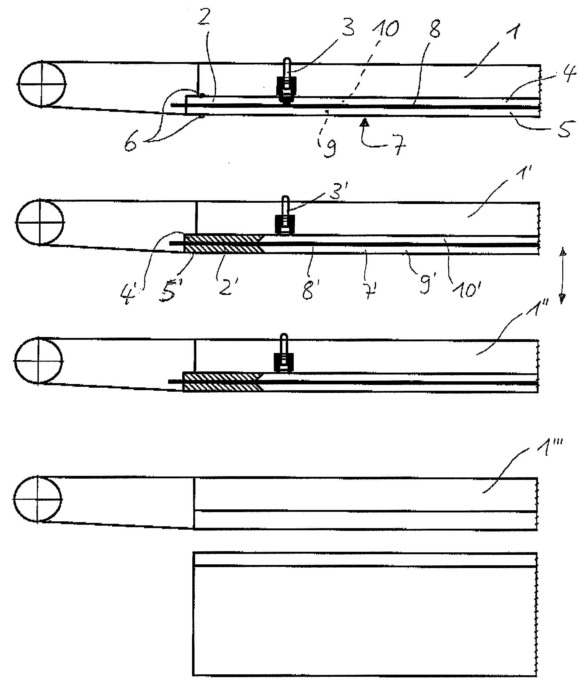
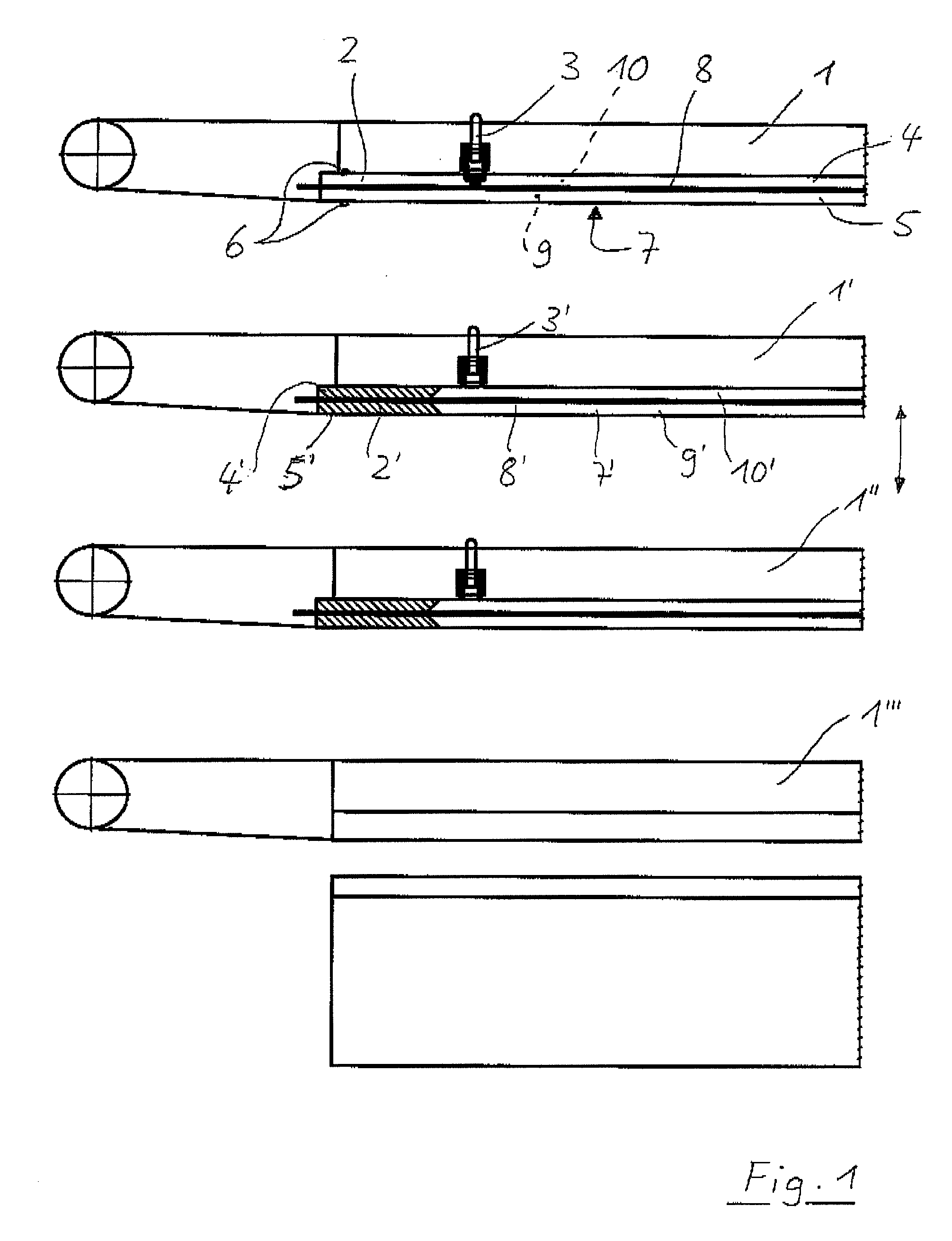
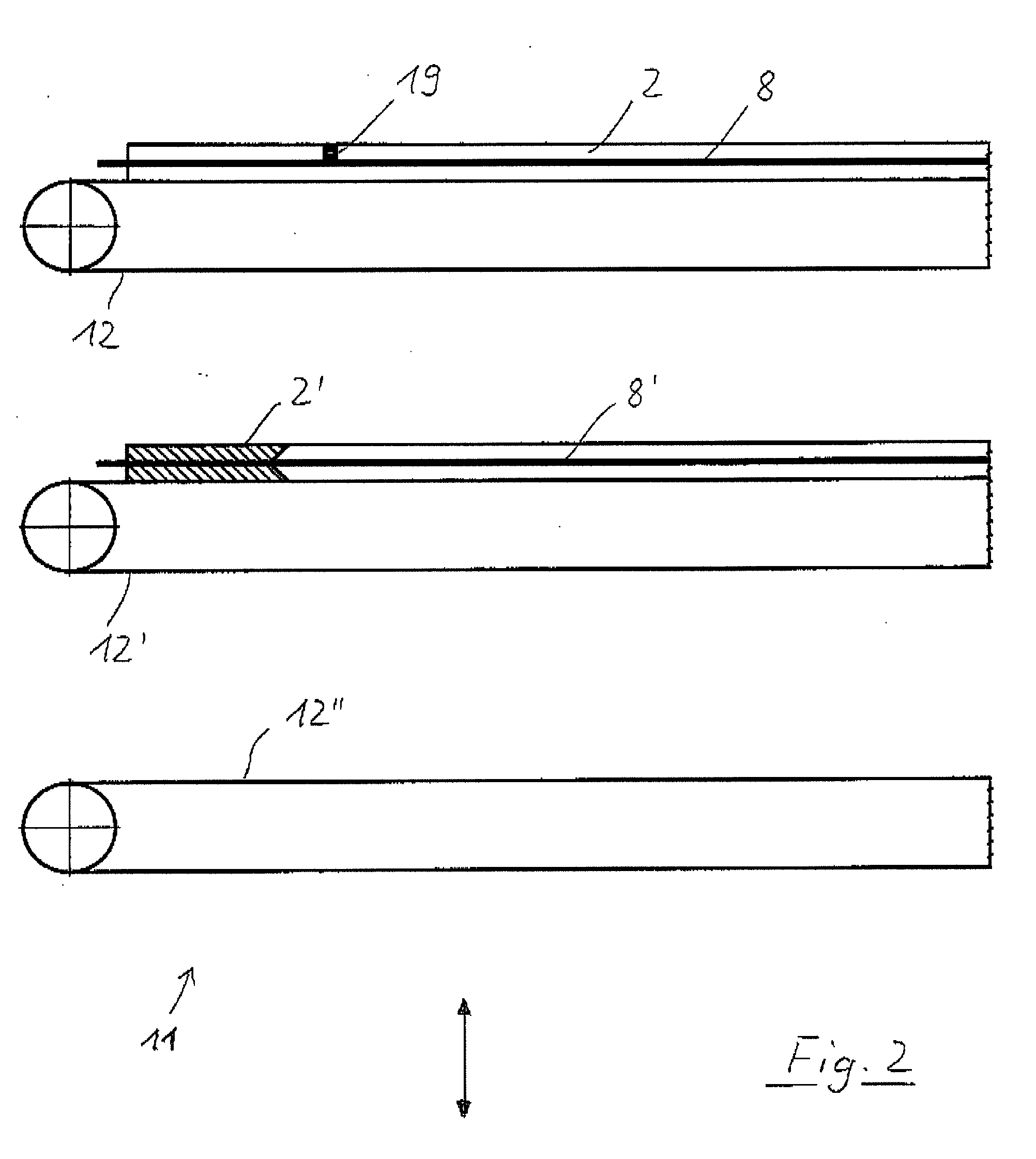
[0031]In FIG. 1, a press constructed according to the invention is shown in a schematic partial diagram, wherein here four heating plates 1, 1′, 1″, 1′″ form three press stages arranged one above the other, wherein the heating plate 1 forms the upper press half of the uppermost press stage and the heating plate 1′ is the lower press half of the uppermost press stage and also simultaneously the upper press half of the middle press stage. A membrane frame 2 that can be handled separately is attached by quick-release closures 3 to the upper press halves, in the example the uppermost press stage, that is, to the uppermost heating plate 1. The quick-release closures 3 are accessible at the side from the outside, so that they can be detached without the heating plate 1 having to cool. They can be made from a quick-release tension lever that is attached so that it can pivot on the heating plate 1 and that can engage in undercut recesses 19 in the membrane frame 2. Obviously, however, vario...


PUM

PropertyMeasurementUnit
Vacuumaaaaaaaaaa

Abstract

A press and a method for laminating essentially plate-shaped workpieces under the effect of pressure and heat. In the closed state, a lower press half and an upper press half form a vacuum chamber utilizing a peripheral, one-part, or multi-part seals. A flexible membrane divides the vacuum chamber into a product half that can be evacuated that holds at least one workpiece and a pressure half that can be pressurized. The membrane is constructed and arranged so that it presses the workpiece directly or indirectly against a bottom side of the vacuum chamber due to a pressure difference generated in the vacuum chamber due to the evacuation of the product half and/or due to the pressurization of the pressure half. The membrane is mounted on a membrane frame that can be handled separately and that is connected detachably to the upper press half and that can be mounted on the membrane frame or tensioned in the frame from outside of the press. At least one membrane frame with a membrane mounted on the frame is stored as a replacement frame outside of the press in a magazine.

Description

CROSS-REFERENCE TO RELATED APPLICATIONS[0001]This application claims the benefit of German Application No. DE 10 2008 025 790.7, filed May 29, 2009, which is incorporated herein by reference as if fully set forth.BACKGROUND[0002]The invention relates to a press for laminating essentially plate-shaped workpieces under the effect of pressure and heat and also to a method for laminating such workpieces under the effect of pressure and heat.[0003]Presses of this type generally comprise a lower press half and an upper press half that form a vacuum chamber in the closed state, by the use of peripheral, one-part or multi-part seals, with the vacuum chamber being divided by a flexible membrane into a product half and a pressure half. The product half of the vacuum chamber is used for holding at least one workpiece and can be evacuated, while the pressure half is formed so that it can be pressurized. Due to a pressure difference in the vacuum chamber generated by the evacuation of the produc...

Claims


Application Information

Patent Timeline
IPC IPC(8): B29C43/20B30B5/02
CPCB29C33/0088Y10T156/1039B29C43/32B29C43/56B29C2043/3411B29C2043/3416B29C2043/3647B29C2043/3649B29C2043/561B29C2043/562B29L2031/3061B29L2031/772B30B5/02B30B7/02B32B37/10B32B37/1009B32B2457/12B29C43/12
Inventor METZGER, DAGMARDAMM, NORBERTDOLKER, GERHARDRENZ, WOLFGANG
Owner ROBERT BURKE GMBH
Why Eureka
Try Eureka